Refrigerant distributor

a technology for refrigerant distributors and distributors, applied in refrigeration components, lighting and heating equipment, domestic cooling equipment, etc., can solve the problems of noise, looseness, and inability to keep the distribution ratio constant, so as to ensure the stability of the distribution ratio, suppress the looseness of the orifice, and ensure the effect of the orifi

Inactive Publication Date: 2010-11-25
SANYO ELECTRIC CO LTD
View PDF13 Cites 15 Cited by
  • Summary
  • Abstract
  • Description
  • Claims
  • Application Information

AI Technical Summary

Benefits of technology

[0013]According to the above configuration, since the stop ring is deflected in contact with the orifice in a state held by the engagement groove, the stop ring can reliably urge the orifice.
[0014]According to the present invention, since the stop ring urges the orifice in the refrigerant flow direction, looseness of the orifice is suppressed, the distribution ratio is kept stably constant, and noise can be reduced.

Problems solved by technology

When this orifice is to be incorporated, it is necessary to fix it at a predetermined position by a predetermined fixing member, but depending on the working accuracy or the like, the incorporated orifice might become loose by a flow of the refrigerant, it is likely that a distribution ratio cannot be kept constant and a noise caused by the looseness is generated.

Method used


Image

  • Refrigerant distributor
  • Refrigerant distributor
  • Refrigerant distributor

Examples


Embodiment Construction

[0021]An embodiment of the present invention will be described below referring to the drawings.

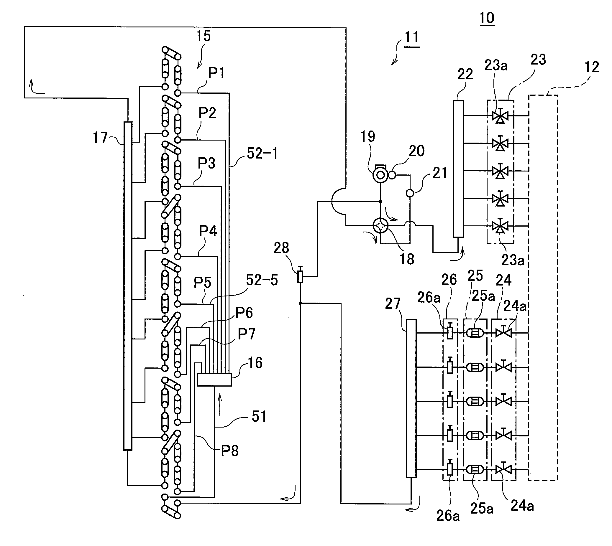
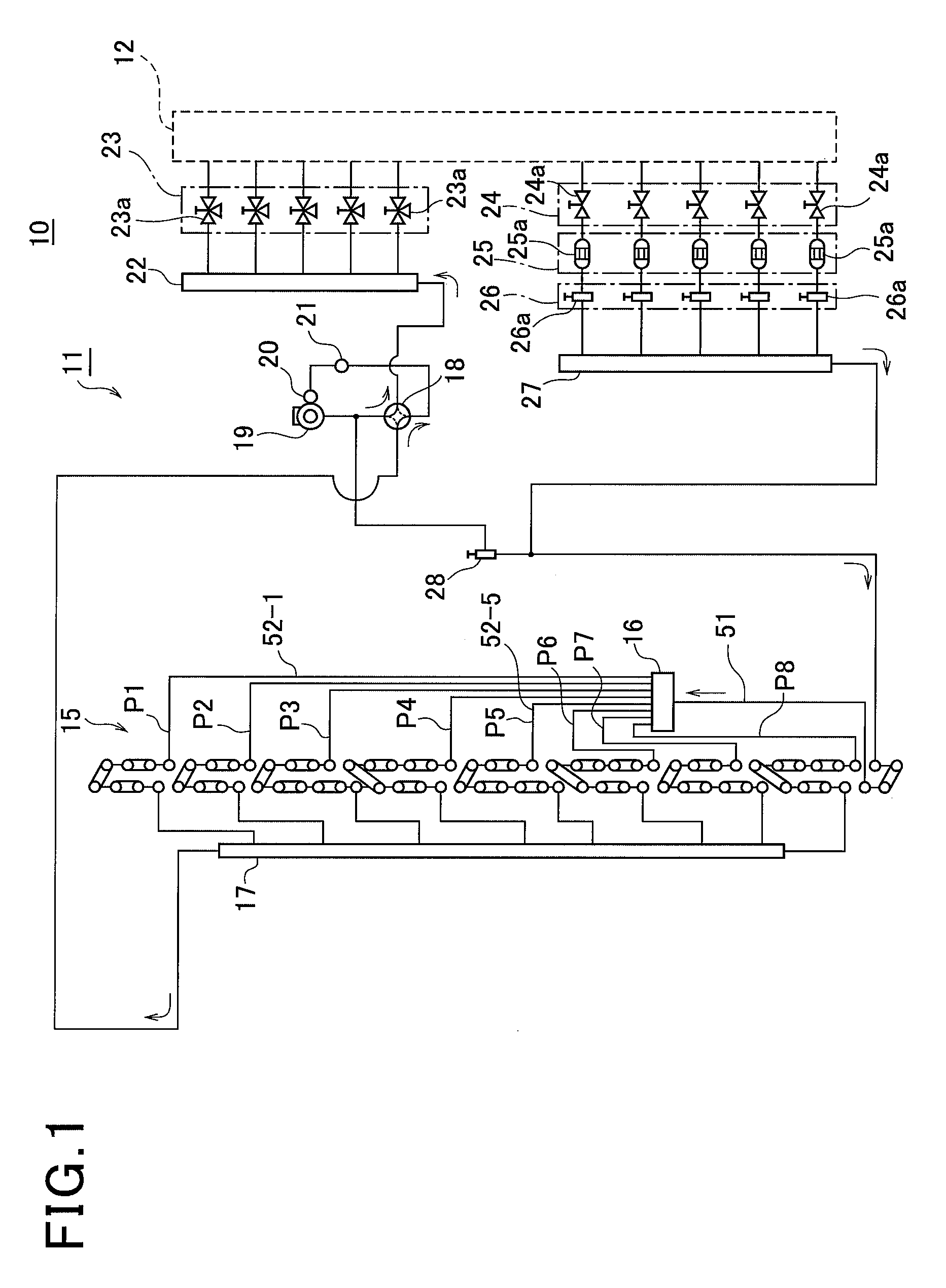
[0022]FIG. 1 is a configuration explanatory diagram of a refrigerant circuit of an air conditioning system of the embodiment.

[0023]The air conditioning system 10 is roughly provided with an outdoor unit 11 and an indoor unit portion 12 provided with a plurality of (five in the embodiment) indoor heat exchangers, not shown.

[0024]The outdoor unit 11 includes an outdoor heat exchanger 15 in which refrigerant piping is provided in plural paths (plural systems) P1 to P8, a refrigerant distributor 16 for distributing the refrigerant to each of the paths P1 to P8 of the outdoor heat exchanger 15 during a heating operation, a merging portion 17 where the refrigerant having flown through each of the paths P1 to P8 during the heating operation is merged, a four-way valve 18 for switching refrigerant channels, a compressor 19 for compressing the refrigerant, an accumulator 20 for separating liquid re...


PUM


Abstract

A conical-shaped distributing member 41 is disposed in a refrigerant distributing portion 32 distributing refrigerant, an orifice 34 is disposed by being positioned at an axis 16X of the conical body, the orifice 34 is held by a stop ring 37, and the stop ring 37 urges the orifice 34 in a flow direction of the refrigerant.

Description

INCORPORATION BY REFERENCE[0001]The present application claims priority under 35 U.S.C. §119 to Japanese Patent Application No. 2009-121592 filed on May 20, 2009. The content of the applications is incorporated herein by reference in its entirety.BACKGROUND OF THE INVENTION[0002]1. Field of the Invention[0003]The present invention relates to a refrigerant distributor and particularly to a refrigerant distributor used in an air conditioner in which refrigerant piping of an outdoor heat exchanger is configured with a multiple path.[0004]2. Description of the Related Art[0005]There is known an outdoor heat exchanger functioning as an evaporator in which refrigerant piping is constructed in a multiple path configuration when a multi-type air conditioner in which a plurality of indoor units are connected in parallel with a outdoor unit is configured, in order to improve heat exchange efficiency of the outdoor unit during heating (for example, JP-A-7-294061).[0006]In the above prior-art o...

Claims


Application Information

Patent Timeline
Patent Type & Authority Applications(United States)
IPC IPC(8): F25D23/00
CPCF25B39/028F25B13/00F25B41/45
Inventor SHIMAOKA, KAZUHIRONAKAJIMA, KENICHIYAMAUCHI, JUNSUGIMOTO, SHINTAROKUSAMA, YOSHIMI
Owner SANYO ELECTRIC CO LTD
Why Eureka
Try Eureka