
Energy transducing apparatus and energy transducing equipment

a technology of energy transducing equipment and energy transducing apparatus, which is applied in the direction of lighting and heating apparatus, light source combinations, and semiconductor/solid-state device details. it can solve the problems of reducing the photoelectric conversion and reducing the efficiency of the solar cell. , to achieve the effect of efficient dissipation of heat generated in operation, preventing the energy transducing apparatus, and improving photoelectric conversion efficiency

Inactive Publication Date: 2010-11-25
NEOBULB TECHNOLOGIES INC
View PDF25 Cites 4 Cited by
  • Summary
  • Abstract
  • Description
  • Claims
  • Application Information

AI Technical Summary

Benefits of technology

[0007]The invention discloses an energy transducing apparatus for efficiently dissipating heat generated in operation, so that the energy transducing apparatus could be prevented from a thermal impact, the photoelectric conversion efficiency could be maintained, and the service life of the energy transducing apparatus could be extended.
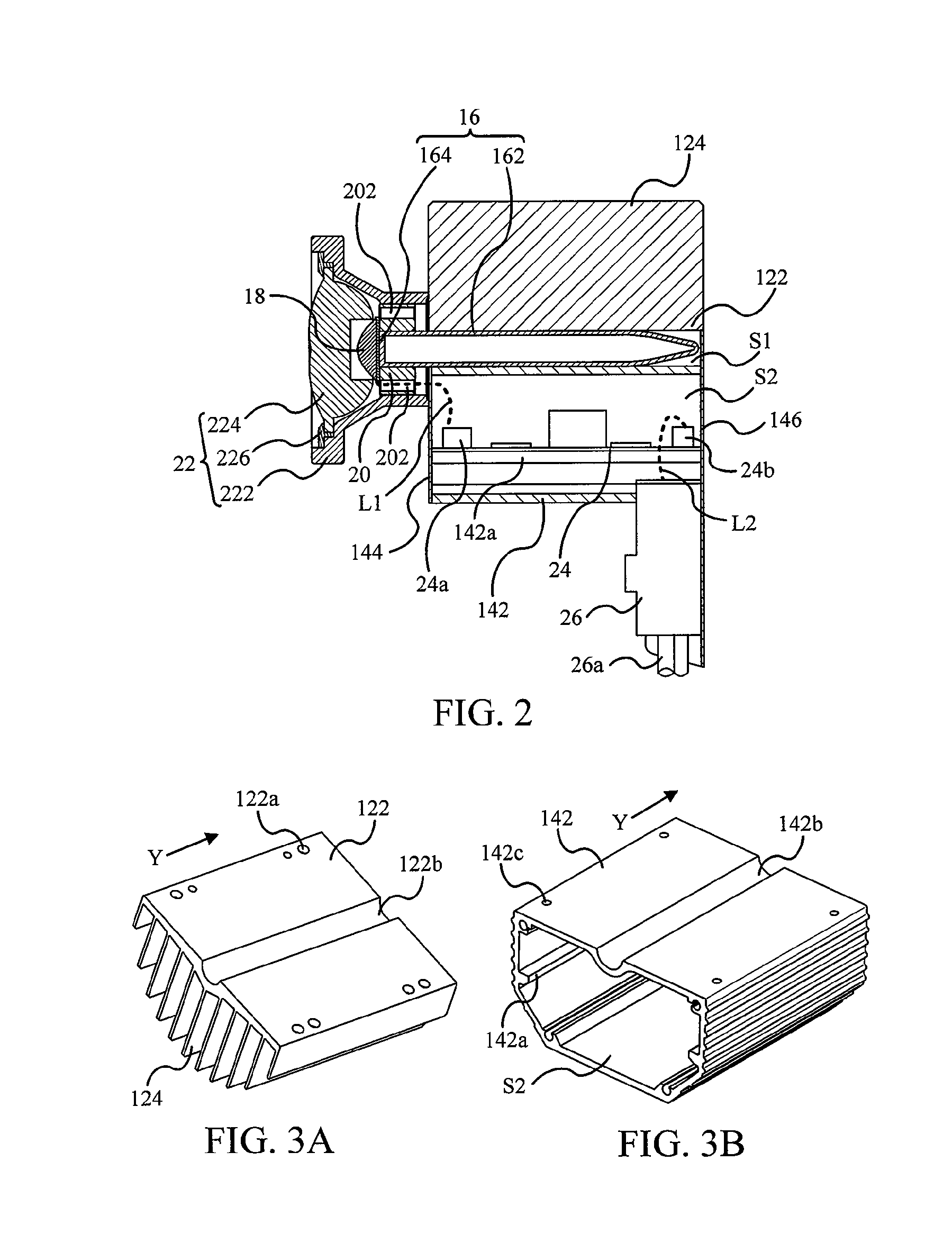
[0009]The heat generated in operating in the energy transducing member could be conducted to the heat pipe through the flat portion contacting the energy transducing member. The conducted heat is transmitted in the heat pipe and then conducted through the contact portion to the first heat-dissipating member and the second heat-dissipating member. Thereby, the heat could be dissipated by the first heat-dissipating member and the second heat-dissipating member. Therein, the fins of the first heat-dissipating member are useful to dissipating heat, so as to raise the heat-dissipating efficiency of the first heat-dissipating member.
[0010]Additionally, the second heat-dissipating member includes a circuit accommodating space for accommodating a control module circuit controlling the energy transducing member. It is of benefit to the modularization of the energy transducing apparatus. The fins parallel to the direction could improve the influence of the setting angle of the energy transducing apparatus on heat dissipation.
[0011]The energy transducing equipment of the invention includes a frame and a plurality of the energy transducing apparatuses. The frame could include a panel with a plurality of holes. The energy transducing apparatuses are disposed on the frame and correspond to the holes. The energy transducing equipment further includes a control module circuit disposed on the frame and electrically connected to the energy transducing apparatuses. The energy transducing apparatuses of the energy transducing equipment are engaged to and mounted on the frame, and they are synchronously controlled by the single control module circuit to perform grouping effect. Further, the energy transducing equipment could become a self-sufficient charging / light-emitting system by equipping with the energy transducing apparatuses of different conversion modes.

Problems solved by technology

However, in a process of transducing solar energy, not all of incident light could be absorbed by a solar cell to be converted into electric current completely.
The too high working temperature will lead to the lower photoelectric conversion efficiency of the solar cell.
With such a vicious circle, more and more solar energy will be lost by heat and the photoelectric conversion efficiency of the solar cell will decrease further.
However it results in other problems, for example, heat dissipation.
If the heat generated by the LEDs in operation could not be dissipated instant, the LEDs will suffer a thermal impact so as to reduce their service life and light-emitting efficiency.
It is negative to saving energy.
Therefore, in the prior art, the heat generated by converting photo energy into electricity could not be dissipated efficiently, so that the photoelectric conversion efficiency of the solar cell could not increase or be maintained, and the solar cell or LED may even be damaged thereby.

Method used


Image

  • Energy transducing apparatus and energy transducing equipment
  • Energy transducing apparatus and energy transducing equipment
  • Energy transducing apparatus and energy transducing equipment

Examples


Embodiment Construction

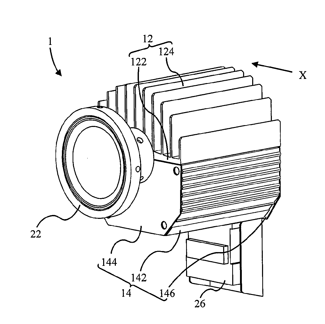
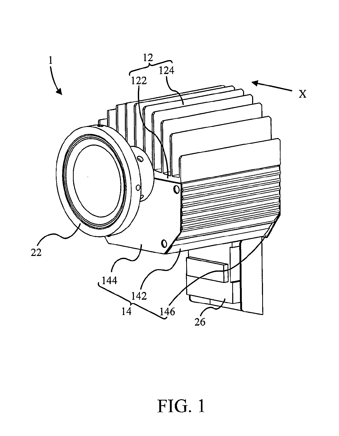
[0032]Please refer to FIG. 1 and FIG. 2. FIG. 1 illustrates an energy transducing apparatus 1 according to a first preferred embodiment of the invention. FIG. 2 illustrates a cross section of the energy transducing apparatus 1. The section penetrates the entire energy transducing equipment 1 symmetrically. The visual angle of FIG. 2 is the direction X as shown in FIG. 1, and a control module circuit 24 and a connector 26 are not cut in FIG. 2 for the simplification of the drawing. Additionally, the cross section of an energy transducing member 18 has also been simplified.

[0033]According to the first preferred embodiment, the energy transducing apparatus 1 includes a first heat-dissipating member 12, a second heat-dissipating member 14, a heat pipe 16, an energy transducing member 18, a carrier 20, an optical adjusting member 22, a control module circuit 24, and a connector 26. The first heat-dissipating member 12 includes a plate body 122 and several fins 124 extending from the plat...


PUM


Abstract

The invention discloses an energy transducing apparatus and an energy transducing equipment grouping a plurality of the energy transducing apparatuses. The energy transducing apparatus includes a heat pipe, a first heat-dissipating member, a second heat-dissipating member, and an energy transducing member. The heat pipe includes a contact portion and a flat portion. The first heat-dissipating member includes a plurality of fins. The second heat-dissipating member is connected to the first heat-dissipating member to form an accommodating space. The contact portion is accommodated in the accommodating space and contacts both the first heat-dissipating member and the second heat-dissipating member. The energy transducing member contacts the flat portion. Thereby, heat generated in operation by the energy transducing member is conducted through the flat portion to the heat pipe and then is dissipated through the first heat-dissipating member, the second heat-dissipating member, and the fins.

Description

BACKGROUND OF THE INVENTION[0001]1. Field of the Invention[0002]The present invention relates to an energy transducing apparatus and an energy transducing equipment, and more particularly, relates to an energy transducing apparatus and an energy transducing equipment using a heat pipe and a combinative heat-dissipating module for dissipating heat.[0003]2. Description of the Prior Art[0004]With the depletion of crude oil, the need for alternative energy becomes important. In consideration of ecosystem impact, solar energy, wind power, and water power become major topics of the development. Therein the solar energy is the most plentiful energy. However, in a process of transducing solar energy, not all of incident light could be absorbed by a solar cell to be converted into electric current completely. A half of the energy of photons is too low (lower than a band gap of a semiconductor) to output a current. Although the other half of the energy of photons is absorbed, except for the r...

Claims


Application Information

Patent Timeline
Patent Type & Authority Applications(United States)
IPC IPC(8): F28D15/04
CPCF21V29/004F21Y2101/02H01L23/427H01L33/648F21V29/006F21V29/763H01L2224/48137H01L2224/48091F21V29/75F21V29/713H01L2924/00014F21Y2115/10F28D15/0275F21V29/51F21Y2113/00
Inventor CHEN, JEN-SHYANLIN, CHUNG-ZEN
Owner NEOBULB TECHNOLOGIES INC
Learn More