
Stator for a polyphase electric machine and method for manufacturing same

a polyphase electric machine and stagger technology, applied in the direction of magnetic circuit rotating parts, magnetic circuit shape/form/construction, cooling/ventilation arrangement, etc., can solve the problem of marking skin effect in the wire, and achieve the effect of low production cost and less waste in cutting

Active Publication Date: 2010-11-25
SEG AUTOMOTIVE GERMANY GMBH
View PDF22 Cites 26 Cited by
  • Summary
  • Abstract
  • Description
  • Claims
  • Application Information

AI Technical Summary

Benefits of technology

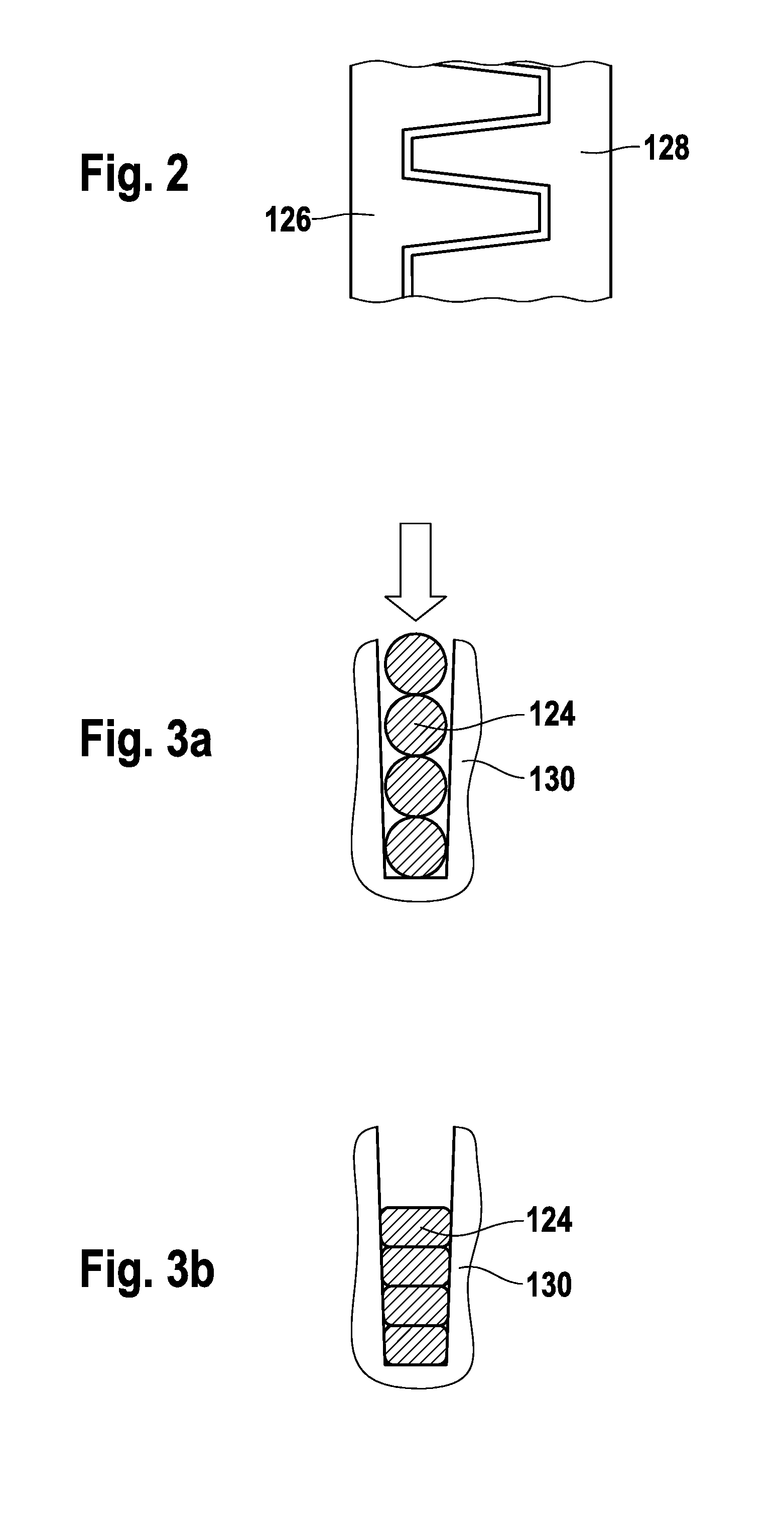
[0011]The method according to the present invention for manufacturing a stator for a polyphase electric machine provides that the core body is formed from a laminated core which is shaped from a strip having slots and teeth, in such a way that the strips are situated in parallel and intermeshed and are cut in pairs out of sheet metal. There is very little waste in cutting, thus allowing inexpensive production.

Problems solved by technology

If fewer slots are provided, the wire diameter increases due to the increasing slot area and results in a marked skin effect in the wire.

Method used


Image

  • Stator for a polyphase electric machine and method for manufacturing same
  • Stator for a polyphase electric machine and method for manufacturing same
  • Stator for a polyphase electric machine and method for manufacturing same

Examples


Embodiment Construction

[0026]FIG. 5 shows a polyphase electric machine 10 designed as a generator such as that used in motor vehicles, for example. Electric machine 10 has a stator 16 having a core body 17 and a winding system 18. Stator 16 is carried by two bearing shields, a drive bearing shield 13.1 facing a pulley 6 and a slip ring beating shield 13.2. Stator 16 radially encompasses a rotor 20 mounted on a shaft 27 and designed as a claw pole rotor. Rotor 20 has two claw pole boards 22, 23, claw fingers 24, 25 designed essentially in a trapezoidal shape extending axially on the outside circumference thereof. Shaft 27 carries the two oppositely polarized claw pole boards, which are situated in the rotor in such a way that their claw fingers extending axially are intermeshed and alternate with one another as north and south poles in the circumferential direction. This results in the claw pole interspaces that are required magnetically between the oppositely magnetized claw fingers situated opposite one ...


PUM

PropertyMeasurementUnit
temperatureaaaaaaaaaa
widthaaaaaaaaaa

Abstract

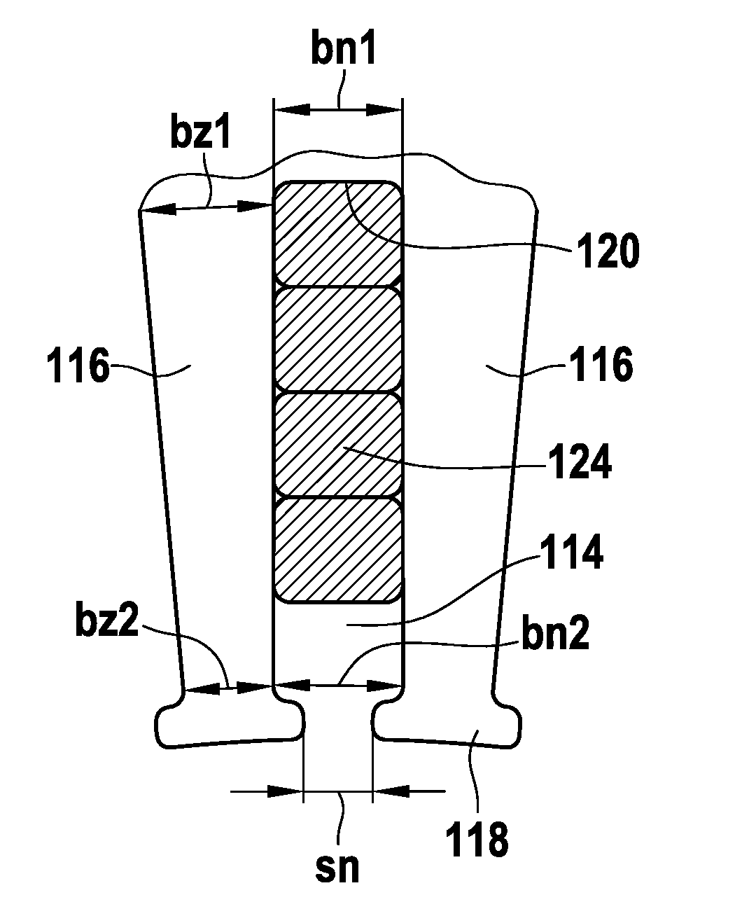
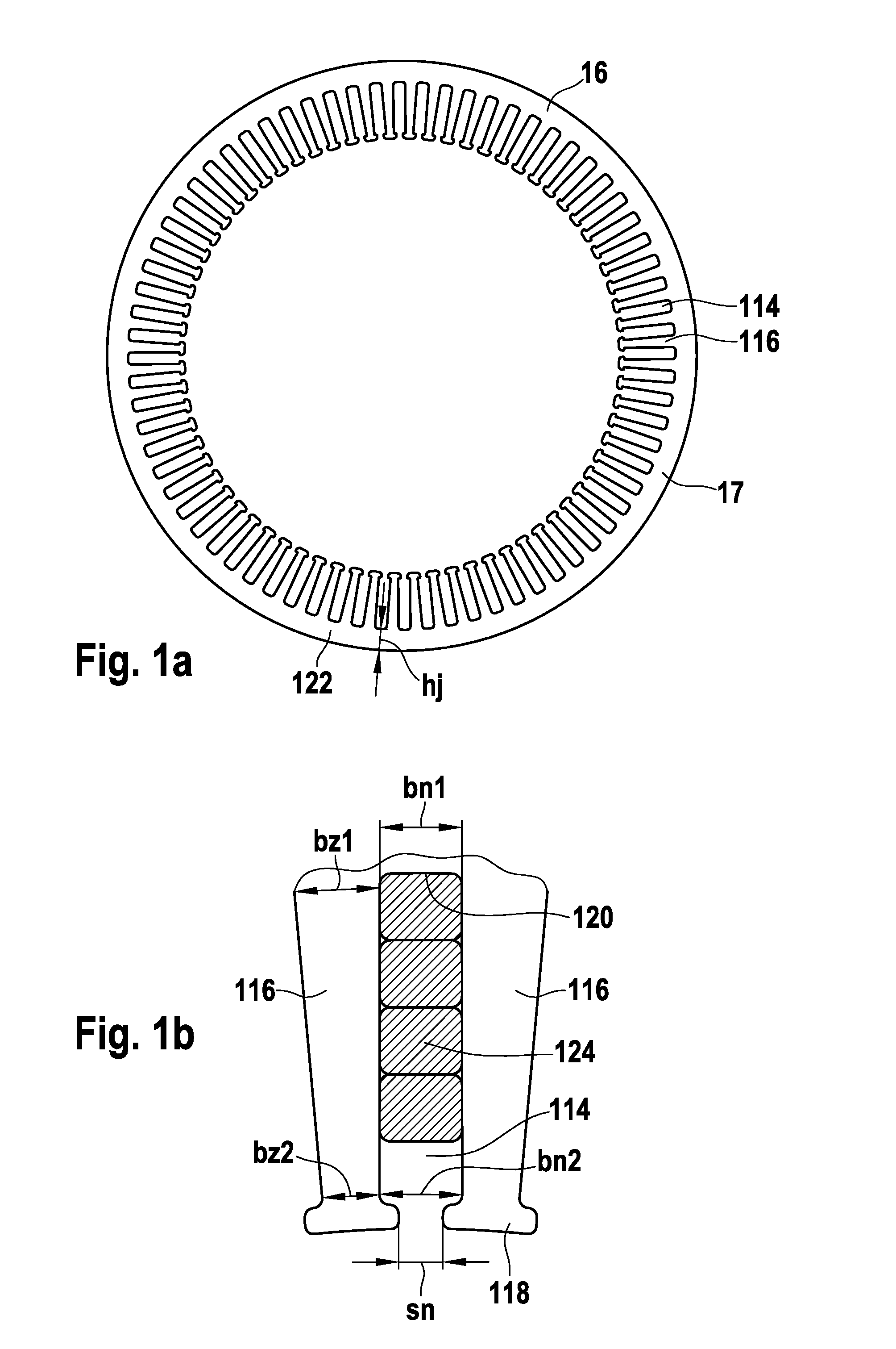
A stator (16) is proposed for a polyphase electric machine, having a core body (17), which is provided with slots (114), which are situated in the radial direction with respect to an axis of rotation of the electric machine on one side of the core body (17) parallel to the longitudinal axis of the core body (17), having a slot width (bn1, bn2) and a stator yoke (122) being provided on the opposite side, with two slots (114) each being separated from one another by a tooth (116) having a tooth width (bz1, bz2) and extending from a slot base (120) to a tooth head (118), these slots (114) being provided to receive at least one coil winding having a plurality of coils that is electrically connected in series and are manufactured from at least one continuous wire (124) without interruption, the ratio (bz2 / hj) of the tooth width (bz2) to the yoke height (hj) at the tooth head (118) being between 0.3 and 0.8 and / or the ratio (bz2 / bn2) of the tooth width (bz2) at the tooth head (118) to the slot width (bn2) at the tooth head (118) being between 0.3 and 3, and / or the ratio (mCu(slot) / mCu(total)) of the copper mass of the wire (124) in the slot (114) to the total copper mass of the wire (124) being between 0.43 and 0.55

Description

BACKGROUND INFORMATION[0001]The present invention relates to a polyphase electric machine, in particular a polyphase generator for motor vehicles, having a stator according to the definition of the species of claim 1 and a method for manufacturing a stator as recited in claim 17.[0002]Various methods and configurations for achieving a high slot filling factor in generators have already been proposed, in which more than 60% of the slot is filled with copper wire, e.g., in DE 103 029 47 A1, DE 103 061 47 A1 or EP1372242A2. U-shaped connector pieces may be inserted axially from one end through the stator slots, bent on the opposite side, and then welded together. This method is very complex and expensive due to the large number of spot welds. Coils may also be inserted into the open slots of a flat metal laminate and then the laminated core together with the coils may be bent into a round shape. This method is also complex and also entails tolerance problems.[0003]An attempt is made wi...

Claims


Application Information

Patent Timeline
Patent Type & Authority Applications(United States)
IPC IPC(8): H02K1/16H02K1/12H02K9/06H02K15/06
CPCH02K1/165Y10T29/49009H02K3/12
Inventor RAU, EBERHARDSHENDL, ALEXANDER
Owner SEG AUTOMOTIVE GERMANY GMBH
Learn More