
Speaker diaphragm, speaker using said diaphragm, and speaker diaphragm manufacturing method

a technology of diaphragm and diaphragm, which is applied in the direction of diaphragm, transducer diaphragm, instrument, etc., can solve the problems of high internal loss of natural, high young's modulus, and insufficient improvement of speaker sound quality, so as to improve the sound quality of the speaker, increase the young's modulus and internal loss of the speaker diaphragm

Active Publication Date: 2010-11-25
PANASONIC CORP
View PDF8 Cites 18 Cited by
  • Summary
  • Abstract
  • Description
  • Claims
  • Application Information

AI Technical Summary

Benefits of technology

[0006]The present invention improves the speaker sound quality by increasing Young's modulus and internal loss of a speaker diaphragm.
[0009]With the above structures, the present invention improves the speaker sound quality by increasing Young's modulus and internal loss of the speaker diaphragm.

Problems solved by technology

Accordingly, a high Young's modulus of inorganic fiber fabric 201 and high internal loss of natural fiber nonwoven fabric 202 are not fully demonstrated, failing to sufficiently improve the speaker sound quality.

Method used


Image

  • Speaker diaphragm, speaker using said diaphragm, and speaker diaphragm manufacturing method
  • Speaker diaphragm, speaker using said diaphragm, and speaker diaphragm manufacturing method
  • Speaker diaphragm, speaker using said diaphragm, and speaker diaphragm manufacturing method

Examples


first exemplary embodiment

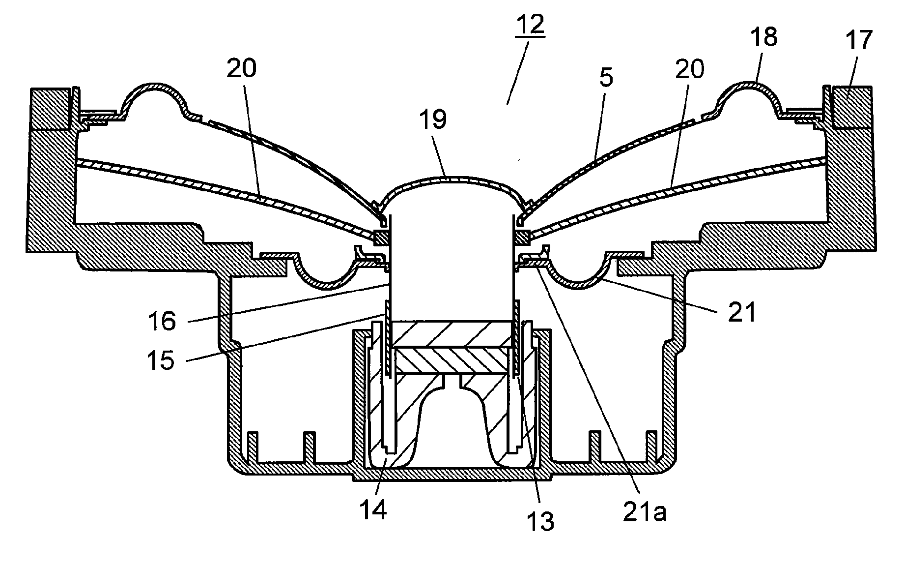
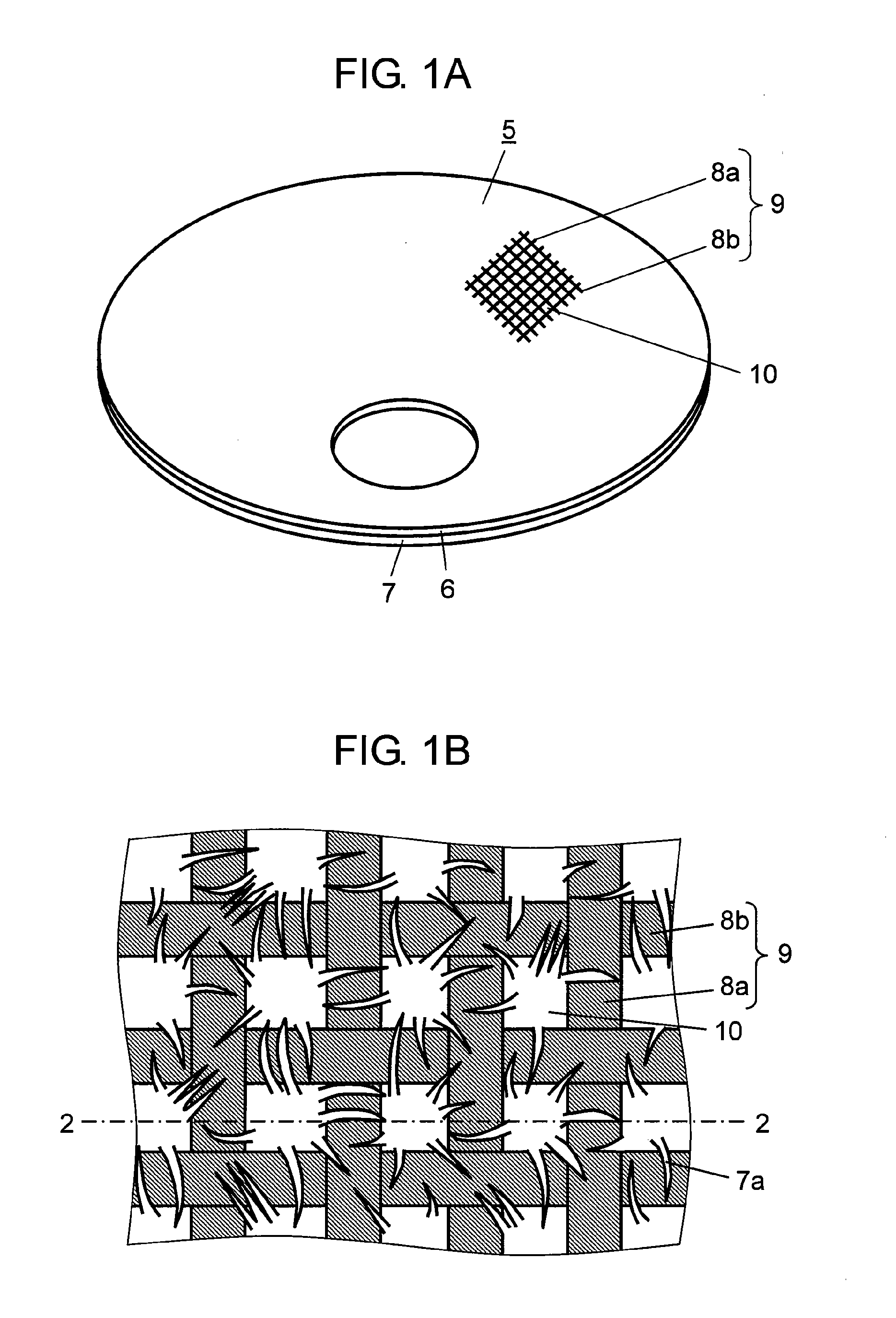
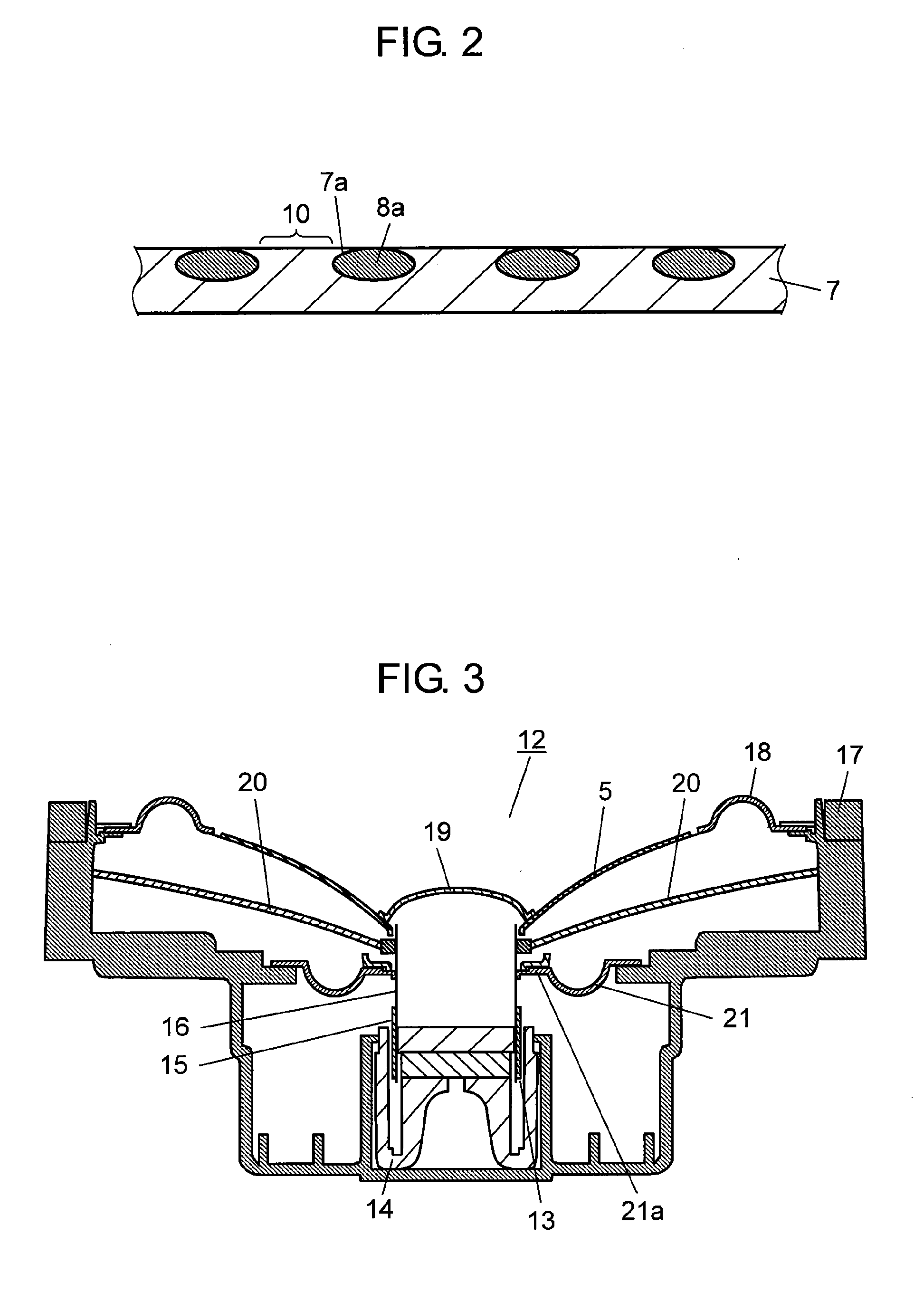
[0036]FIG. 1A is a perspective view of a speaker diaphragm in the first exemplary embodiment of the present invention. In FIG. 1A, speaker diaphragm 5 has a two-layer structure of fabric layer 6 and paper layer 7. Fabric layer 6 is formed by weaving two types of thread 9, i.e., warp 8a and weft 8b, in a reticular pattern. These reticular stripes are exposed on the surface of speaker diaphragm 5. Thermosetting resin (not illustrated) exists inside and on outer circumference of these warp 8a and weft 8b. Warp 8a and weft 8b themselves and fabric layer 6 formed by weaving these threads are hardened by thermally curing this thermosetting resin. This fabric layer 6 contains at least one of high-strength fibers, such as aramid fiber, polyester fiber, acrylic fiber, cotton fiber, carbon fiber, glass fiber, and silk fiber. Thermosetting resin is resin containing at least one of phenol resin, acrylic resin, epoxy resin, and vinylester resin.

[0037]Paper layer 7 is formed by mixing aramid fibe...

second exemplary embodiment

[0070]FIG. 9A is a perspective view of a speaker diaphragm in the second exemplary embodiment of the present invention. In FIG. 9A, speaker diaphragm 101 has a two-layer structure of fabric layer 102 and nonwoven fabric layer 103. Fluff 104 of nonwoven fabric layer 103 is entangled with fabric layer 102, as described later. Fabric layer 102 is formed by weaving two types of thread 107, i.e., warp 105 and weft 106 in a reticular pattern. These reticular stripes are exposed on the surface of speaker when speaker diaphragm 101 is disposed on the speaker. Thermosetting resin (not illustrated) exists inside and on outer circumference of these warp 105 and weft 106. Warp 105 and weft 106 themselves and fabric layer 102 formed by weaving these threads are hardened by thermally curing this thermosetting resin.

[0071]This fabric layer 102 contains at least one of high-strength fiber such as aramid fiber, polyester fiber, acrylic fiber, cotton fiber, carbon fiber, glass fiber, and silk fiber. ...


PUM


Abstract

A speaker diaphragm includes a fabric layer in which impregnated thermosetting resin is thermally cured, and a paper layer integrated on a rear face of this fabric layer. Fluffs of the paper layer filling stitches of the fabric layer are entangled with threads of the fabric layer from a surface of the fabric layer, and are firmly fixed by thermosetting resin. This integrates the layers in the state that the paper layer is filled in the stitches of the fabric layer. Accordingly, internal loss and Young's modulus of the speaker diaphragm can be increased. As a result, the speaker sound quality can be improved.

Description

TECHNICAL FIELD[0001]The present invention relates to speaker diaphragms and speakers using the speaker diaphragm.BACKGROUND ART[0002]A speaker diaphragm employed in a speaker requires a high Young's modulus and moderate internal loss in order to reproduce high-quality sounds from the speaker.[0003]FIG. 17 is a perspective view of a conventional speaker diaphragm. In FIG. 17, speaker diaphragm 204 is configured with laminated body 203 including inorganic fiber fabric 201 and natural fiber nonwoven fabric 202 laminated on the bottom face of inorganic fiber fabric 201. This speaker diaphragm intends to achieve excellent characteristics in both Young's modulus and internal loss by attaching inorganic fiber fabric 201 that has low internal loss but high Young's modulus and natural fiber nonwoven fabric 202 that has low Young's modulus but high internal loss. This technology is disclosed in Patent Literature 1.[0004]However, aforementioned conventional speaker diaphragm 204 is configured...

Claims


Application Information

Patent Timeline
Patent Type & Authority Applications(United States)
IPC IPC(8): H04R7/00H04R9/06G10K13/00
CPCH04R7/125H04R2307/021H04R2307/029H04R31/003
Inventor FUNAHASHI, OSAMU
Owner PANASONIC CORP
Learn More