Method for calculating pressures in a fluid stream through a tube section, especially a blood vessel with atherosclerotic plaque

a fluid stream and pressure calculation technology, applied in the field of fluid stream pressure calculation in the fluid stream through the tube section, can solve the problems of high computing capacity and complicated methods, and achieve the effect of facilitating the prediction of plaque rupture risk

Inactive Publication Date: 2010-11-25
CABRA TECH
View PDF2 Cites 128 Cited by
  • Summary
  • Abstract
  • Description
  • Claims
  • Application Information

AI Technical Summary

Benefits of technology

[0012]It is the object of the invention to provide a simple, automated method and system for calculation of pressure variations in fluid tubes for use in simulations of longitudinal and radial stress distribution around surface irregularities. Especially, it is the object of the invention to provide specific methods and systems for simulation of stress distribution and blood pressure in blood vessels in order to facilitate predictions of plaque rupture risk.

Problems solved by technology

This method is complicated and requires high computing capacity due to the evaluation of the 3-D model.

Method used


Image

  • Method for calculating pressures in a fluid stream through a tube section, especially a blood vessel with atherosclerotic plaque
  • Method for calculating pressures in a fluid stream through a tube section, especially a blood vessel with atherosclerotic plaque
  • Method for calculating pressures in a fluid stream through a tube section, especially a blood vessel with atherosclerotic plaque

Examples


first embodiment

[0018]In a first embodiment, the method implies measuring the fluid pressure at the upstream end and measure the fluid velocity at the downstream end and include these measurements in the boundary conditions. For example, the method implies measuring the fluid velocity at the upstream end, and calculating on the basis of the pressure distribution in the tube section the expected fluid velocity at the upstream end, and comparing the measured fluid velocity and the expected fluid velocity at the upstream end as part in an evaluation procedure for the validity of the pressure calculation.

second embodiment

[0019]In a second embodiment, the method implies measuring the fluid velocity at the upstream end and wherein the boundary conditions include the measured fluid velocity at the upstream end and an estimated pressure at the downstream end. For example, the method implies measuring the fluid velocity at the downstream end, and calculating on the basis on the pressure distribution in the tube section the expected fluid velocity at the downstream end, and comparing the measured fluid velocity and the expected fluid velocity at the downstream end as part in an evaluation procedure for the validity of the pressure calculation.

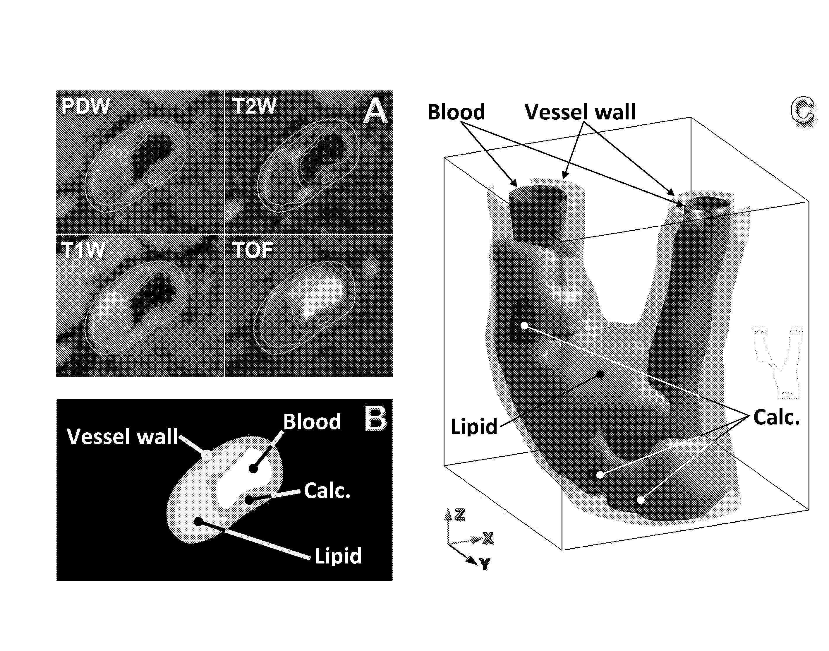
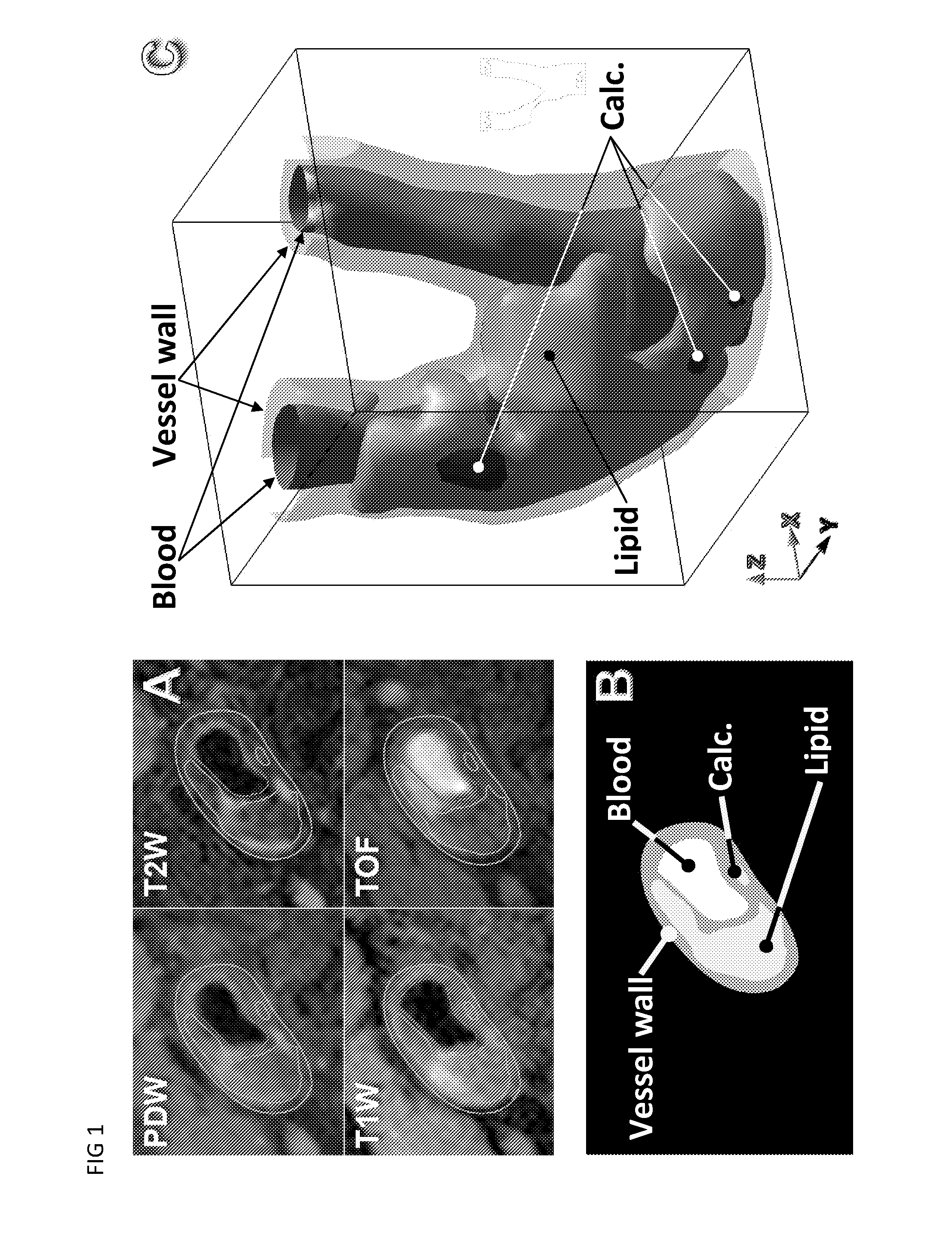
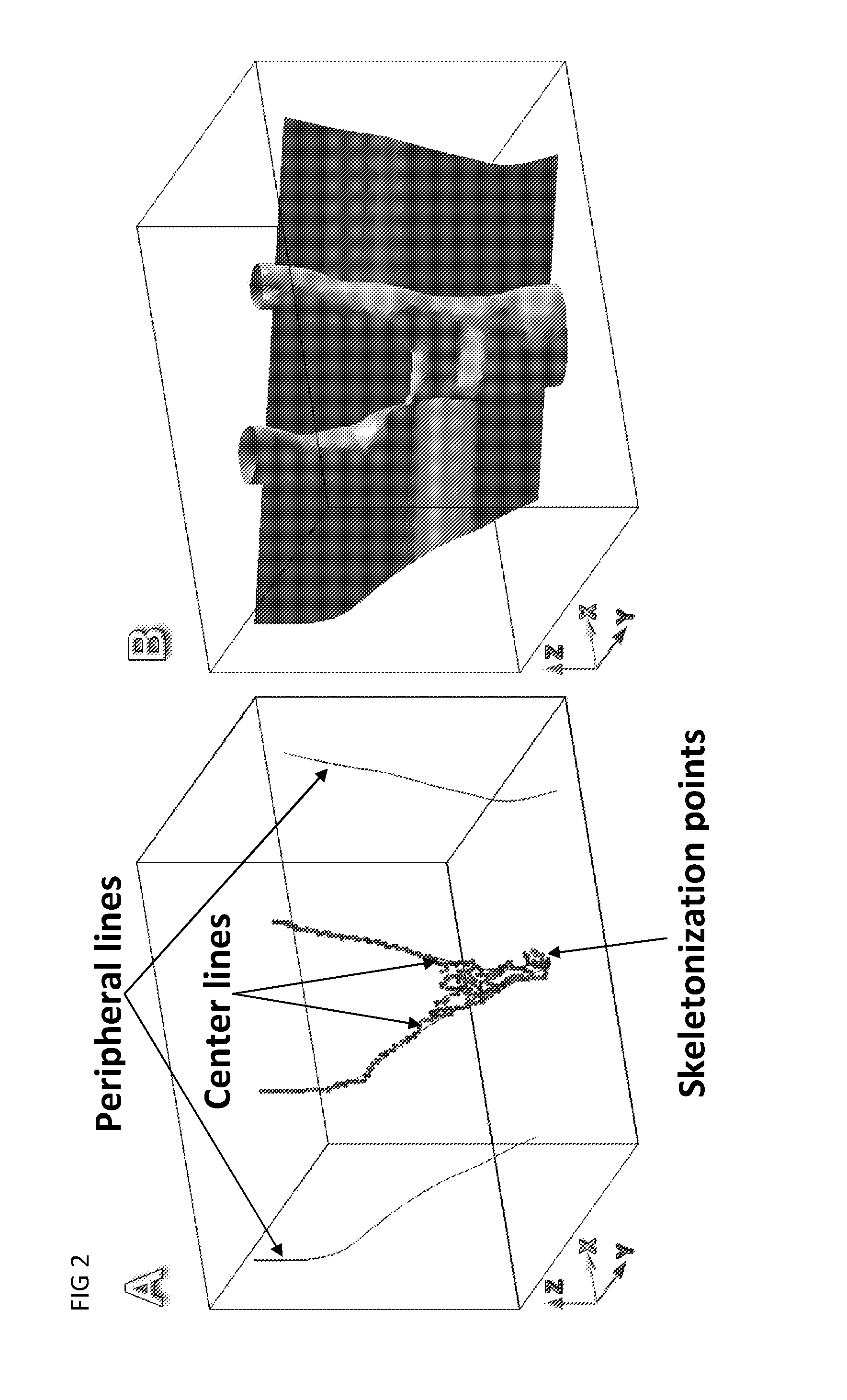
[0020]In a third embodiment, the method implies using the derived longitudinal pressure distribution achieved by either the first or second embodiment as a boundary condition for calculating stresses and deformations in cross-sectional 2D models corresponding to the available image scans, for example MRI scans. Though both the first and second embodiments may be used...


PUM


Abstract

A method for calculating pressures in a fluid streaming through a tube section from an upstream end to a downstream end of the tube section, the method comprising scanning the tube section with a scanner and providing a plurality of 2D scanning images along the tube section with an inlet and at least two arms, by a computer program on the basis of the 2D images automatically N calculating a 3D image of the tube section by using interpolating between the 2D images, by a computer program performing a 2D sectional image cut through the 3D image, the image cut following the fluid stream, calculating in the sectional image cut a fluid pressure distribution along multiple locations inside the tube on the basis of given boundary conditions, the boundary conditions including fluid velocity or fluid pressure at the upstream end.

Description

FIELD OF THE INVENTION[0001]The present invention relates to a method for calculating pressures in a fluid stream through a tube section, especially a blood vessel with atherosclerotic plaque.BACKGROUND OF THE INVENTION[0002]Atherothrombosis is the leading cause of death and severe disability worldwide (Rosamond et al., 2007). The disease generates fatty deposits inside vessel walls (lipid cores) covered by a protective fibrous cap—the atherosclerotic plaque. If the cap ruptures, blood clots are formed which may be carried downstream to lodge in small-diameter vessels. Disrupted blood flow results in causing heart attacks or strokes. Currently, the risk of cap rupture is assessed using the degree of luminal narrowing. This fails to take the morphology of the plaque into account. Indeed, unstable or vulnerable plaques are known to possess large lipid cores and thin fibrous caps. Morphology such as this generates severe internal stresses in the fibrous cap. In vitro studies have shown...

Claims


Application Information

Patent Timeline
Patent Type & Authority Applications(United States)
IPC IPC(8): A61B5/021G16Z99/00
CPCA61B5/02028A61B5/055G06F19/3437G06T2207/30104G06T2207/10072G06T2207/20044G06T7/0012G16H50/50G16Z99/00
Inventor KOCK, SAMUEL ALBERGNYGAARD, JENS VINGEBESENBACHER, FLEMMINGKIM, WON YONG
Owner CABRA TECH
Why Eureka
Try Eureka