Downward Firing Oxygen-Fuel Burners for Glass Melting Furnaces

a technology of oxygen-fuel burners and glass melting furnaces, which is applied in the direction of combustion types, lighting and heating apparatuses, manufacturing tools, etc., can solve the problems of significant disturbance of the surface of limited heat that conventional oxygen-fuel burners can transfer to the batch materials or molten glass through convection, and environmental and quality concerns, so as to achieve maximum convective and radiant heat transfer

Inactive Publication Date: 2010-12-02
ZHANG ZHIFA +1
View PDF14 Cites 71 Cited by
  • Summary
  • Abstract
  • Description
  • Claims
  • Application Information

AI Technical Summary

Benefits of technology

[0009]The present invention relates to a furnace for melting a solid mixture in order to provide a molten product. The furnace is comprised of a bath enclosure holding the molten product, a combustion space above the bath enclosure, and a downward firing burner. In particular, the downward firing burner may be placed in the breast wall of the combustion space at a location and an angle that may maximize convective and radiant heat transfer to the bath's surface.

Problems solved by technology

Due to this design, the amount of heat that conventional oxygen-fuel burners can transfer to the batch materials or molten glass through convection is limited.
However, there are two major concerns with this placement.
First, due to their high velocities, the flames and products of combustion leaving the oxygen-fuel burners may cause significant disturbances in the surface of the batch materials or molten glass.
These disturbances may range from batch material entrainment to changes in the characteristics of the molten glass, thus creating environmental and quality concerns.
Second, when the oxygen-fuel burners are located in pairs on opposite breast walls, the opposing oxygen-fuel flames may impinge on each other and be deflected toward the roof of the glass melting furnace, potentially damaging its refractory and adversely impacting the integrity of the glass melting furnace and its service life.
However, since the temperature of the refractory walls is typically limited to 3,000° F. while the oxygen-fuel flame temperature may be 4,790° F., much of the radiant intensity is lost.

Method used


Image

  • Downward Firing Oxygen-Fuel Burners for Glass Melting Furnaces
  • Downward Firing Oxygen-Fuel Burners for Glass Melting Furnaces
  • Downward Firing Oxygen-Fuel Burners for Glass Melting Furnaces

Examples


Embodiment Construction

[0021]The following detailed description is of the best currently contemplated modes of carrying out the invention. The description is not to be taken in a limiting sense, but is made merely for the purpose of illustrating the general principles of the invention, since the scope of the invention is best defined by the appended claims.

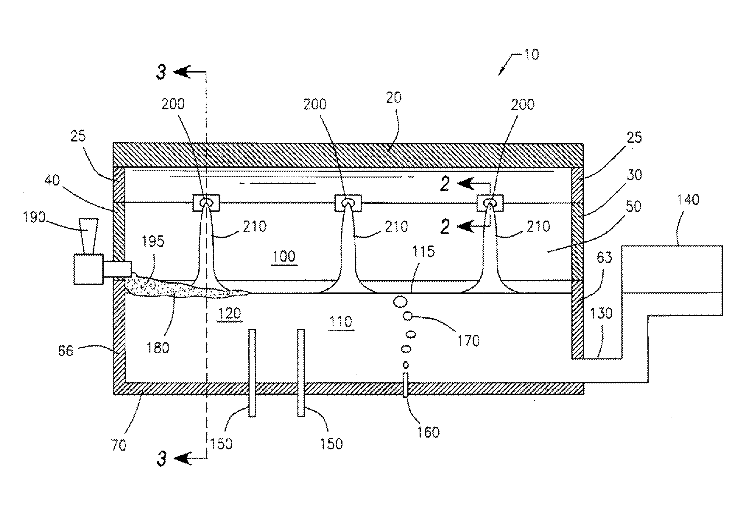
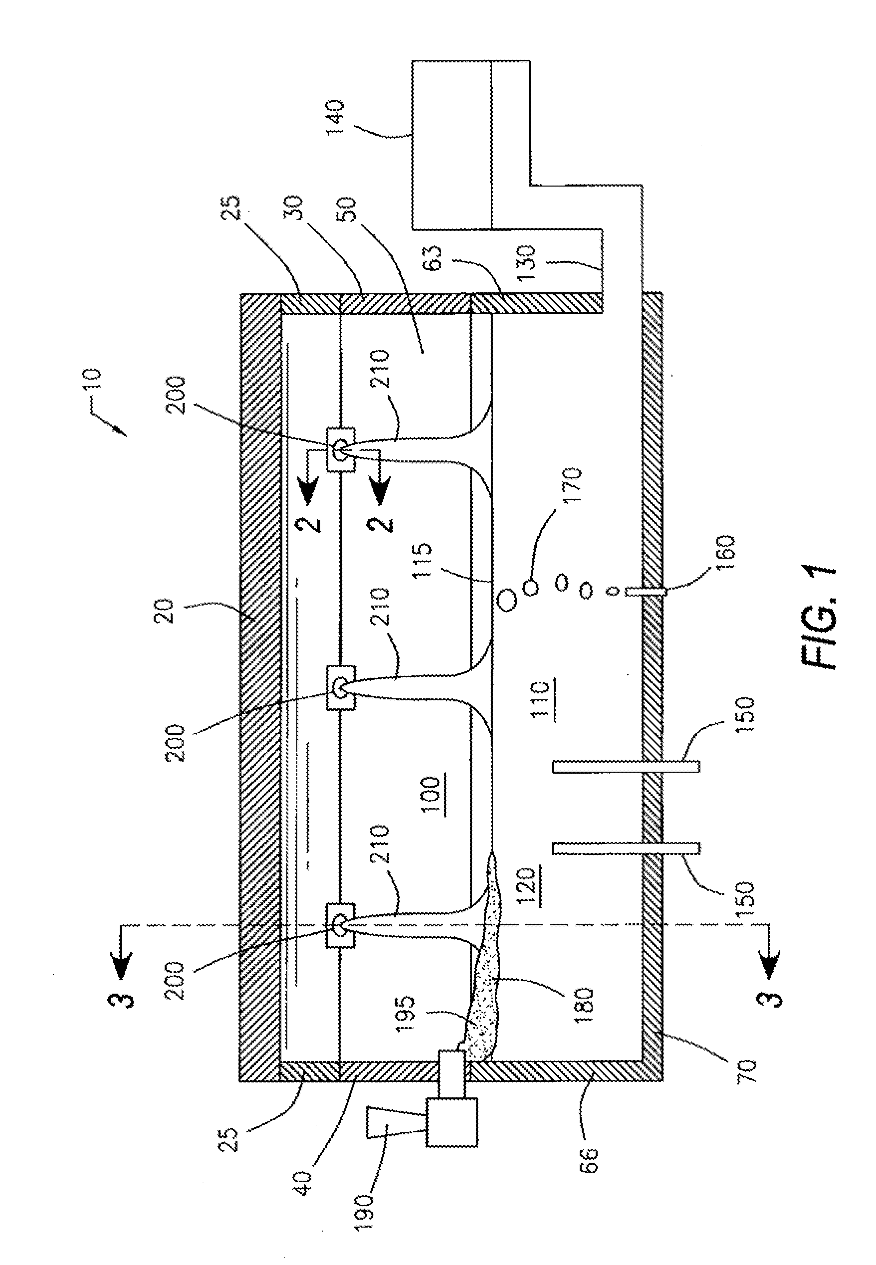
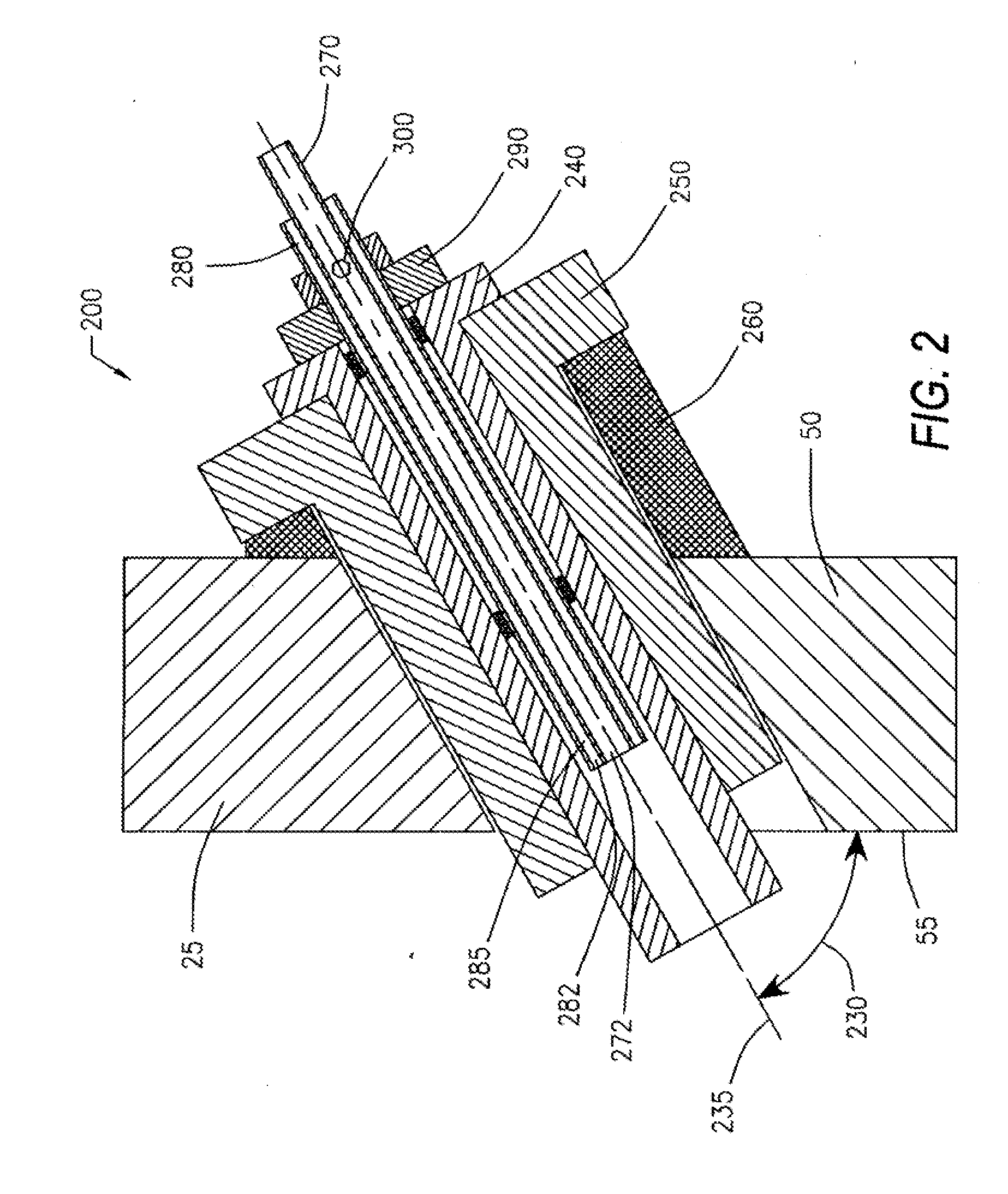
[0022]Broadly, the current invention includes systems, devices, and methods for enhancing the performance of glass melting furnaces. More particularly, the invention relates to the placement of downward firing oxygen-fuel burners at an angle in the breast walls of the glass melting furnace so that the oxygen-fuel flames impinge on the upper surface of the glass bath. The invention thus maximizes the amount of heat transferred to the batch materials or molten glass while ensuring the formation of high quality glass products and preventing damage to the glass melting furnace and its components. It will be appreciated that the detailed construction of the ...


PUM

PropertyMeasurementUnit
angleaaaaaaaaaa
distanceaaaaaaaaaa
flame temperatureaaaaaaaaaa

Abstract

This invention relates to a glass melting furnace with downward firing oxygen-fuel burners placed in the breast walls of the combustion space and adjacent to the skew block. The downward firing oxygen-fuel burner may be placed at an angle so that the oxygen-fuel flame from the downward firing oxygen-fuel burner impinges on the upper surface of the glass bath. The placement and angle of the downward firing oxygen-fuel burner may maximize the amount of heat transferred to the batch cover or the molten glass, ensure the formation of high quality glass products, and protect the integrity of the downward firing oxygen-fuel burners and the glass melting furnace.

Description

FIELD OF THE INVENTION[0001]This invention relates to the use of downward firing oxygen-fuel burners to improve the performance of glass melting furnaces. More particularly, the downward firing oxygen-fuel burners may be placed in the breast walls of a glass melting furnace at a location and an angle that maximizes the amount of heat transferred to the batch materials or molten glass. This invention also relates to a process for operating the downward firing oxygen-fuel burners.BACKGROUND OF THE INVENTION[0002]In order to produce glass products, raw glass-forming materials, which are also known as batch materials, are melted to form molten glass. This melting occurs in a high-temperature enclosure known as a glass melting furnace. The molten glass is subsequently delivered to the forming operations, where the final glass products are shaped.[0003]A glass melting furnace is a refractory enclosure comprised of a glass bath and a combustion space. The glass bath is comprised of a front...

Claims


Application Information

Patent Timeline
Patent Type & Authority Applications(United States)
IPC IPC(8): C03B3/00C03B5/00
CPCC03B5/2353F23C5/02Y02E20/344F23D14/22F23D14/32F23C5/08Y02P40/57Y02P40/50
Inventor ZHANG, ZHIFAYANG, HAO
Owner ZHANG ZHIFA
Why Eureka
Try Eureka