
Oxygen conserving oxygen delivery system

Active Publication Date: 2010-12-02
IPG
View PDF35 Cites 15 Cited by
  • Summary
  • Abstract
  • Description
  • Claims
  • Application Information

AI Technical Summary

Benefits of technology

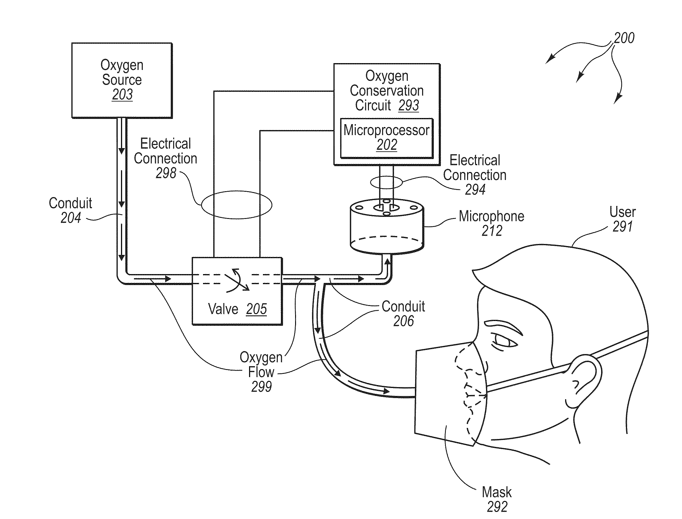
[0017]The electronically controlled valve has at least an open setting and a closed setting. The open setting permits the flow of oxygen from the first port to the second port. The closed setting prevents the flow of oxygen from the first port to the second port.
[0020]The microcontroller is also electrically connected to the valve controller via an electrical connection. The valve controller controls the electronically controlled valve. The valve control can transition the electronically controlled valve from the closed setting to the open setting, can maintained the electronically controlled valve in the open setting, can transition the electronically controlled valve from an open setting to a closed setting, and can maintain electronically controlled valve in the closed setting.

Problems solved by technology

The need to conserve oxygen is a result of the understanding that continuous, long term oxygen therapy is expensive because of the large quantities of oxygen that need to be provided to a user.
Less sophisticated oxygen therapy systems provide oxygen at a continuous rate without interruption.
The result is that all oxygen supplied to the user during exhalation is wasted.
Furthermore, these systems do not adjust for rates or depth of inspiration by the user.
However, these systems have numerous drawbacks which prevent them from serving all the functions of an acceptable oxygen conservation device.
These drawbacks include, but are not limited to, a failure to adequately adapt to breathing depth (force) of the person using the system.
They also fail to take into account changes that occur due to variations in altitude of the user.
They also fail to compensate for changes in battery strength, and fail to adequately conserve battery power.
Many of these membrane type sensors are able to handle the pressure of the valve passing the oxygen, but can be expensive to manufacture and then calibrate for use.
Potential problems encountered when using the pulse-demand system include either no oxygen flow from the device or decreased oxygen saturation in the patient.
If no oxygen flow is detected, then possible causes may include a depletion of the gas supply, an obstruction or disconnection of the connecting tubing, or an inability of the device to detect the patient's effort to breath.
A decrease in the patient's oxygen saturation should always be a cause for alarm and may indicate a change in the patient's medical status, tachypnea, or a failure in the device.
Additionally, pulsed-dose systems are typically costly and have increased complexity.
The increased complexity results in a variety of technical problems.
For example, pulsed-dose systems may fail to increase oxygen dosage during periods of increased need, such as, for example, exercise, stress, illness, etc.
They also have complicated setup procedure which can result in disconnections, improper placement of the device, possible device failures, etc.

Method used


Image

  • Oxygen conserving oxygen delivery system
  • Oxygen conserving oxygen delivery system
  • Oxygen conserving oxygen delivery system

Examples


Embodiment Construction

[0036]The present invention extends to methods, systems, computer program products, and circuits for conserving oxygen during the delivery of oxygen to a user. In some embodiments, an oxygen delivery system operates to regulate a flow of oxygen during an inspiration event of a respiratory cycle. The system includes an oxygen source, an electronically controlled valve, a valve controller, a microphone, an oxygen delivery component (e.g., a cannula or facemask), a filter, and a microprocessor. A first portion of conduit pneumatically couples the oxygen source first pneumatic port of the electronically controlled valve. A second portion of conduit couples a second port of the electronically controlled valve to the oxygen delivery component and to a microphone.

[0037]The electronically controlled valve has at least an open setting and a closed setting. The open setting permits the flow of oxygen from the first port to the second port. The closed setting prevents the flow of oxygen from t...


PUM


Abstract

The present invention extends to methods, systems, computer program products, and circuits for conserving oxygen during the delivery of oxygen to a user. Embodiments of the invention use a microphone to detect breathing sounds indicative of different portions of a breathing cycle. Sounds not related to the breathing cycle are filtered out of the signal. Using the breathing sounds, a microprocessor differentiates inspiration from other portions of the breathing cycle. When inspiration is detected, a valve is transitioned to permit the flow of oxygen from an oxygen source to a user to deliver an appropriate bolus of oxygen. The microprocessor can also detect fault conditions, such as, for example, apnea, failure to deliver a bolus of oxygen, and restrictions in the flow of oxygen from the oxygen source to a user.

Description

CROSS-REFERENCE TO RELATED APPLICATIONS[0001]The present application claims priority to U.S. Provisional Patent Application No. 60 / 056,770, filed May 28, 2008, and titled “OXYGEN CONSERVING DEVICE”, which is herein incorporated by reference in its entirety.BACKGROUND OF THE INVENTION[0002]The state of the art in oxygen therapy is replete with systems that attempt to conserve oxygen being supplied to a user. The need to conserve oxygen is a result of the understanding that continuous, long term oxygen therapy is expensive because of the large quantities of oxygen that need to be provided to a user. For example, oxygen conservation in aviation applications saves both space and weight.[0003]Less sophisticated oxygen therapy systems provide oxygen at a continuous rate without interruption. The result is that all oxygen supplied to the user during exhalation is wasted. The wasted oxygen can be substantial considering that approximately two thirds of the respiratory cycle is spent in exha...

Claims


Application Information

Patent Timeline
IPC IPC(8): A61M16/00G10K11/16
CPCA61M16/00A61M2016/0015A61M2202/0208A61M2205/18A61M2205/3375A61M2205/3553A61M16/204A61M2205/52A61M2205/581A61M2205/583A61M2205/8206A61M16/0677A61M2205/3584A61M16/101A61M16/0051A61M2202/03A61M16/024A61M2202/0007
Inventor DECKER, THOMAS D.MCLAUGHLIN, PATRICK L.
Owner IPG
Learn More