
Water-based combustion-supporting coal gas frying-pan kiln and Mg catalysis low-CO2RO2 emission technology

An emission technology, water-based technology, applied in the direction of combustion using catalytic materials, combustion method, combustion type, etc., can solve the problems of unassisted combustion, increase the sensible heat loss of flue gas emission, harmfulness, etc., and achieve the effect of maintaining activity

Active Publication Date: 2013-04-17
管理
View PDF7 Cites 8 Cited by
  • Summary
  • Abstract
  • Description
  • Claims
  • Application Information

AI Technical Summary

Problems solved by technology

[0002] At present, the known coal, oil, and gas combustion technologies all use traditional air combustion-supporting thermal equipment technology except for a small amount of metallurgical furnaces and other oxygen blowing or pure oxygen combustion-supporting technologies. Since most of the 78.9% inert gases in the air are nitrogen, not only It does not help combustion, but also "takes" a large amount of oxygen in the furnace (every 1 ton of N in the combustion product reacts to generate NO 2 , it needs to consume more than 2.29 tons of oxygen, resulting in an increase of 11,000 m to the excess air volume of the boiler and kiln 3 , based on the exhaust gas temperature of 200°C at 15°C, the additional incremental heat exhaust gas is 18,500 nm 3 , the sensible heat loss is as high as 256.32kJ / m 3 The total is 1.13 million kcal) and generates nitrogen oxides that are extremely harmful to human health (according to a research report by an authoritative organization in Western Europe in the 1990s that sounded the alarm to all mankind, if according to the Western European region at the end of the 20th century If the nitrogen oxide pollution situation is left unchecked, then the males in this environment will gradually lose their reproductive capacity), and at the same time, the sensible heat loss of flue gas emissions will also be greatly increased

Method used


Image

  • Water-based combustion-supporting coal gas frying-pan kiln and Mg catalysis low-CO2RO2 emission technology
  • Water-based combustion-supporting coal gas frying-pan kiln and Mg catalysis low-CO2RO2 emission technology
  • Water-based combustion-supporting coal gas frying-pan kiln and Mg catalysis low-CO2RO2 emission technology

Examples


Embodiment Construction

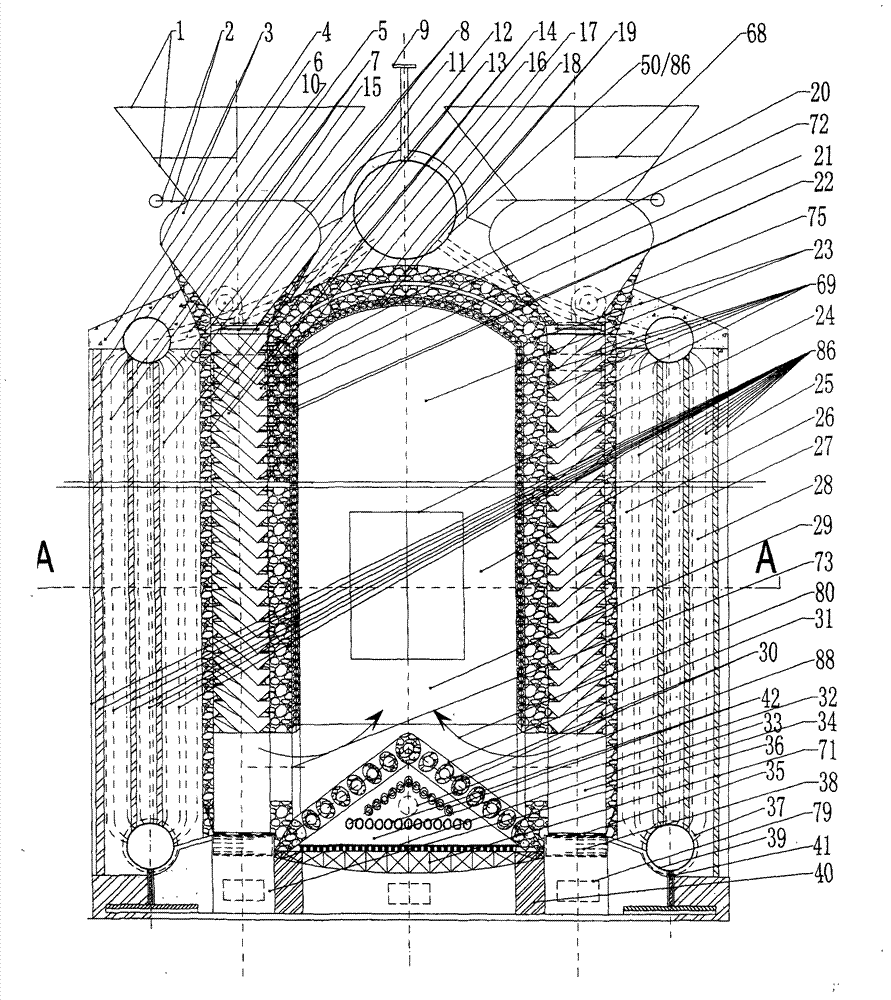
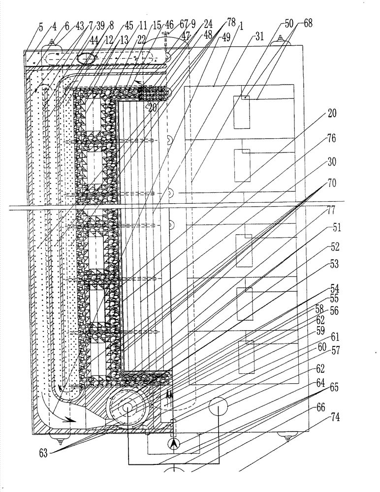
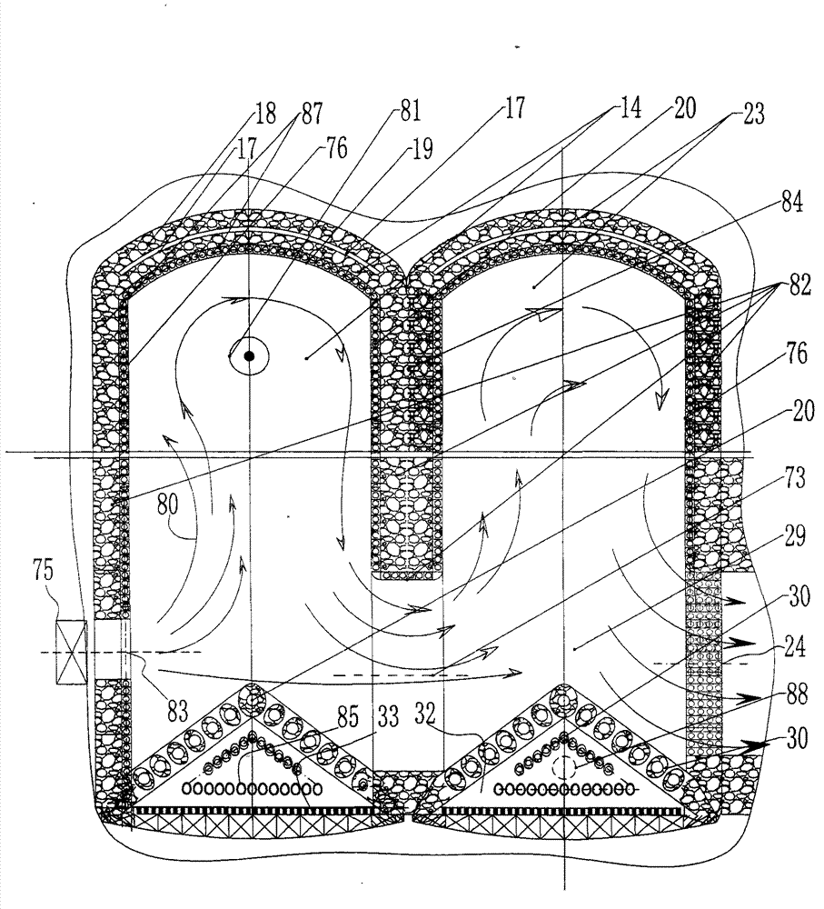
[0035] exist figure 1 Among them, the top-mounted pot 50, the two sides are symmetrical through the joint pipe 15, and there are "upper header 10-convection tube bundle 12-lower header 39" which are subjected to the high-temperature furnace wall 8 and the low-temperature furnace wall 7 tortuous diversion flow radiation chamber 26 , high-temperature convection chamber 27, low-temperature convection chamber 28, water circulation heat exchange system 86 of three-pass furnace 78, dry heat furnace 70 within the boiler, with the vortex vacuum furnace 23 as the center of symmetry, the bottom of the chamber 23 is provided with a cooling triangular grate 31, and the grate 31 cavity The two waists of the triangle are equipped with refractory grate bars and grate slope steps, and there are recooled ash grates 42 inside, and the bottom edge is a dislocated double grate 33, and the steel structure joist 71 is set under the grate 33; the inner peripheral side of the chamber 23 is lined with...


PUM


Abstract

The invention provides a water-based combustion-supporting coal gas frying-pan kiln and Mg catalysis low-CO2RO2 emission technology. Air is not required to be blown in but water vapor completely replaces combustion-supporting coal, oil and gas, magnesium oxide mineral powder and the like are decomposed in a gasification hearth to obtain magnesium vapor, Mg, MgO, H, C, O and other vapor mixed flows detained in the eddy-current cavity at the top in the eddy current vacuum hearth achieve fully catalytic reaction to realize steady operation of a series of reaction dynamic equilibrium in the vacuum hot-carbon ultra-high temperature dry heat furnace environment of magnesium group vapor catalysis matched with mixed vaporization combustion, so that six-in-one ultra-high-efficiency energy conservation and environmental protection are achieved, the generated heat is exchanged in a three-pass hearth by a 'drum-header-tube bank' pressure-bearing assembly outside the dry heat furnace, and all superheat walls of the inner lining of the dry heat furnace are cooled in the way that an auxiliary engine drives recycling of flue gas.

Description

technical field [0001] The invention relates to a water-based combustion-supporting gas oil boiler furnace and Mg catalyzed low CO 2 RO 2 Emission technology, especially the use of water vapor to completely replace the combustion-supporting coal, oil, and gas without blowing in air. The magnesium vapor produced by burning magnesium oxide ore powder is used in the vortex chamber at the top of the vortex vacuum furnace. The steam mixed flow of vortex Mg, Mg O, H, C, O, etc. fully catalyzes the reaction, and the furnace is closed intermittently or continuously to push coal or jet oil injection and feed dolomite powder and other magnesium-containing raw materials in proportion, and the liquid is mixed in proportion The magnesium group steam catalyzed by gasification combustion is in the dry heat furnace environment of vacuum hot carbon and ultra-high temperature, and the heat is produced by the water-based heat exchange output of the "drum-header-tube bundle" pressure-bearing ass...

Claims


Application Information

Patent Timeline
IPC IPC(8): F23C13/08
Inventor 管理
Owner 管理
Learn More