
Multi-layer micro-energy harvester and method of making the same

a multi-layer, energy harvester technology, applied in the direction of electrostatic generators/motors, influence generators, electrical apparatus, etc., can solve the problems of drie not being a three-dimensional (3-d) fabrication process, limiting the space of a micro-harvester, and reducing the efficiency of the process, so as to achieve the effect of simple and repetitive steps

Active Publication Date: 2010-12-02
ZHANG GANG
View PDF12 Cites 14 Cited by
  • Summary
  • Abstract
  • Description
  • Claims
  • Application Information

AI Technical Summary

Benefits of technology

The patent text describes a multi-layer structure that can extract and convert ambient vibration energy into electrical energy. The structure includes multiple layers of variable capacitors and a moving mass layer. The layers are bonded together to form a multi-layer variable capacitor. The structure can be anchored to a substrate and the movable electrode can be suspended above the substrate. The technical effects of the invention include increased capacitance, larger capacitance, and higher power density.

Problems solved by technology

However, this is usually not the case because of the limitations of current silicon microfabrication technologies.
In some cases, not only is a space for a micro-harvester is restricted, but its footprint area is also restricted as well.
In addition, DRIE is not a truly three-dimensional (3-D) fabrication process.
However, the difficulty of forming a multi-layer electrostatic harvester is that its each variable capacitor layer contains discrete silicon features shown in FIG. 4 where two fixed electrodes 138 and 140 do not mechanically connect with a moving electrode 142 on the same layer.
Obviously this kind of layer cannot be made separately as discrete features will fall down.
This is a fundamental drawback in standard bulk micromachining plus silicon bonding.
However, this post separation treatment only works for special designs.
In addition, it is not a reliable and desirable approach as the removal of the silicon mechanical connections is the last step of the process.
If it fails, all previous work will be wasted.
However, DRIE can be performed only once on each side of a layer, which restricts to form more complex structures.
Besides, this solution involves many process steps and may face difficult operations, low throughput and low yield.
As the converted power is proportional to the moving mass of an energy harvester, using silicon as the material of harvesters has an intrinsic drawback due to its low density (2.33 g / cm3).
But it would be quite challenging to electroplate a layer of metal just on the silicon movable electrode of a microfabricated comb capacitor type harvester.
However, making a precise micro-scale tungsten alloy mass and then precisely attaching it on a micromachined silicon harvester seem not to be a feasible mass production approach.

Method used


Image

  • Multi-layer micro-energy harvester and method of making the same
  • Multi-layer micro-energy harvester and method of making the same
  • Multi-layer micro-energy harvester and method of making the same

Examples


first embodiment

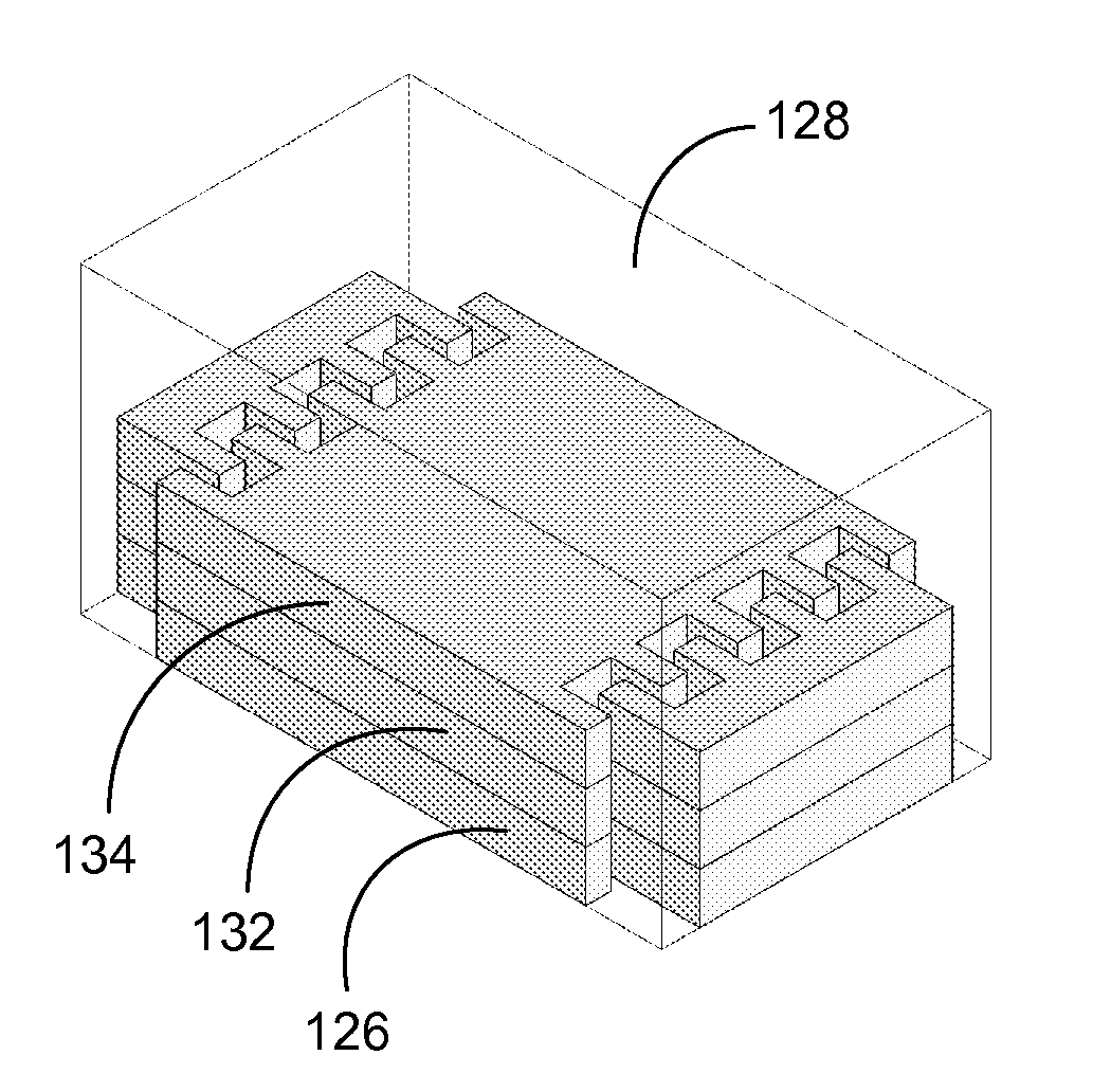
[0057]FIG. 5 schematically illustrates a perspective view of a multi-layer electrostatic energy harvester structure 143 that comprises three bonded variable capacitor layers 144 (top), 146 (middle), and 148 (bottom). In this embodiment, The three capacitor layers are made essentially of silicon. The three capacitor layer structures are essentially identical. Each capacitor layer comprises two fixed finger electrodes, one movable finger electrode (also as a moving mass), and two spring structures that are not shown and may have the spring structures shown in FIG. 1. Fixed electrodes 150, 152, 154, 156, 158, and 160 are for the capacitor layers 144, 146, and 148, respectively. Movable electrodes 162, 164, and 166 are for the capacitor layers 144, 146, and 148, respectively. Each movable electrode has two sets of fingers which form two variable comb capacitors with the two fixed electrodes on each capacitor layer. The fingers of each comb capacitor are arranged to be interdigitated. In...

third embodiment

[0067]FIG. 11 schematically illustrates a multi-layer electrostatic energy harvester structure 250 that comprises two separate variable capacitor layers 252 and 254. The capacitor layer 252 is above the capacitor layer 254. Their orientation is essentially orthogonal. These two capacitor layers are independent and do not have mechanical connections between them. The structure 250 can be viewed as a combination of two independent single-layer energy harvester structures that have similar structures to the single-layer structure 100 in FIG. 1. Both capacitor layers are made essentially of silicon. Each of the capacitor layers is anchored to a substrate (not shown) via anchor components (partially shown). Spring structures of both capacitor layers are not shown in FIG. 11 and may have the same spring structures shown in FIG. 1. The spring structures are also anchored to the substrate via anchor components (not shown and may refer to FIGS. 1A-1B). Again, their spring structures may be d...


PUM


Abstract

The embodiments of the present invention are directed to multi-layer electrostatic energy harvester structures for extracting and converting more ambient vibration energy into electrical energy and / or extracting ambient vibration energy at a plurality of different vibration frequencies or frequency ranges. In some embodiments, a multi-layer electrostatic energy harvester structure comprises a plurality of bonded variable capacitor layers. In some embodiments, a multi-layer electrostatic energy harvester structure comprises a plurality of variable capacitor layers and at least one moving mass layer that are bonded together. Still in some embodiments, a multi-layer electrostatic energy harvester structure comprises a plurality of separate variable capacitor layers. One preferred multi-layer microfabrication method is provided to make multi-layer electrostatic energy harvester structures disclosed in the present invention, comprising: forming a plurality of separate layers that compose a multi-layer electrostatic energy harvester structure wherein each of the plurality of separate layers comprises at least one material and wherein at least one of the plurality of separate layers comprises a sacrificial material; bonding at least the plurality of separate layers together; and removing at least a portion of the sacrificial material.

Description

CROSS-REFERENCE TO RELATED APPLICATIONS[0001]This application claims the benefit of provisional patent application Ser. No. 61 / 057,201, filed May 29, 2008 by the present inventor.STATEMENT REGARDING GOVERNMENT SPONSORED RESEARCH[0002]This invention was made with U.S. Government support under grant number NSF / SBIR 0711677 from the National Science Foundation. The Government has certain rights in this invention.FIELD OF THE INVENTION[0003]This invention generally relates to the field of vibration-based energy harvesters. More particularly, it relates to multi-layer electrostatic energy harvester structures and to a method of making such structures.BACKGROUND OF THE INVENTION[0004]With advances in ultra-low power IC (integrated circuits) design and MEMS (Microelectromechanical Systems) technologies, the size of electronic circuits and devices and the energy needed to drive them have been being reduced significantly. Harvesting energy from the environment to power microelectronics devic...

Claims


Application Information

Patent Timeline
Patent Type & Authority Applications(United States)
IPC IPC(8): H02N11/00
CPCH02N1/08B81B3/0021
Inventor ZHANG, GANG
Owner ZHANG GANG
Learn More