Coil assembly and magnetic element with shielding function

a shielding function and coil technology, applied in the direction of coils, transformers/inductance details, inductances, etc., can solve the problems of emi problem affecting neighboring circuits or electronic components, easy to cause emi problem, etc., to reduce the overall volume of the magnetic element, the possibility of causing emi problem is minimized, and the effect of enhancing the window utilization of the magnetic cor

Active Publication Date: 2010-12-02
DELTA ELECTRONICS INC
View PDF9 Cites 28 Cited by
  • Summary
  • Abstract
  • Description
  • Claims
  • Application Information

AI Technical Summary

Benefits of technology

[0006]It is an object of the present invention to provide a coil assembly with a shielding function. The coil assembly is used in a magnetic element. By using the coil assembly of the present invention, the possibility of causing the EMI problem is minimized, the window utilization of the magnetic core is enhanced, and the overall volume of the magnetic element is reduced.

Problems solved by technology

Since the switching power supply apparatus has some switch elements, the magnetic element is readily suffered from an electromagnetic interference (EMI) problem.
The EMI problem is detrimental to the neighboring circuits or electronic components.
Especially, because of the parasitic capacitor between the primary side and the secondary side of the transformer, the transformer is a main reason of causing the EMI problem in the switching power supply apparatus.

Method used


Image

  • Coil assembly and magnetic element with shielding function
  • Coil assembly and magnetic element with shielding function
  • Coil assembly and magnetic element with shielding function

Examples


Embodiment Construction

[0020]The present invention will now be described more specifically with reference to the following embodiments. It is to be noted that the following descriptions of preferred embodiments of this invention are presented herein for purpose of illustration and description only. It is not intended to be exhaustive or to be limited to the precise form disclosed.

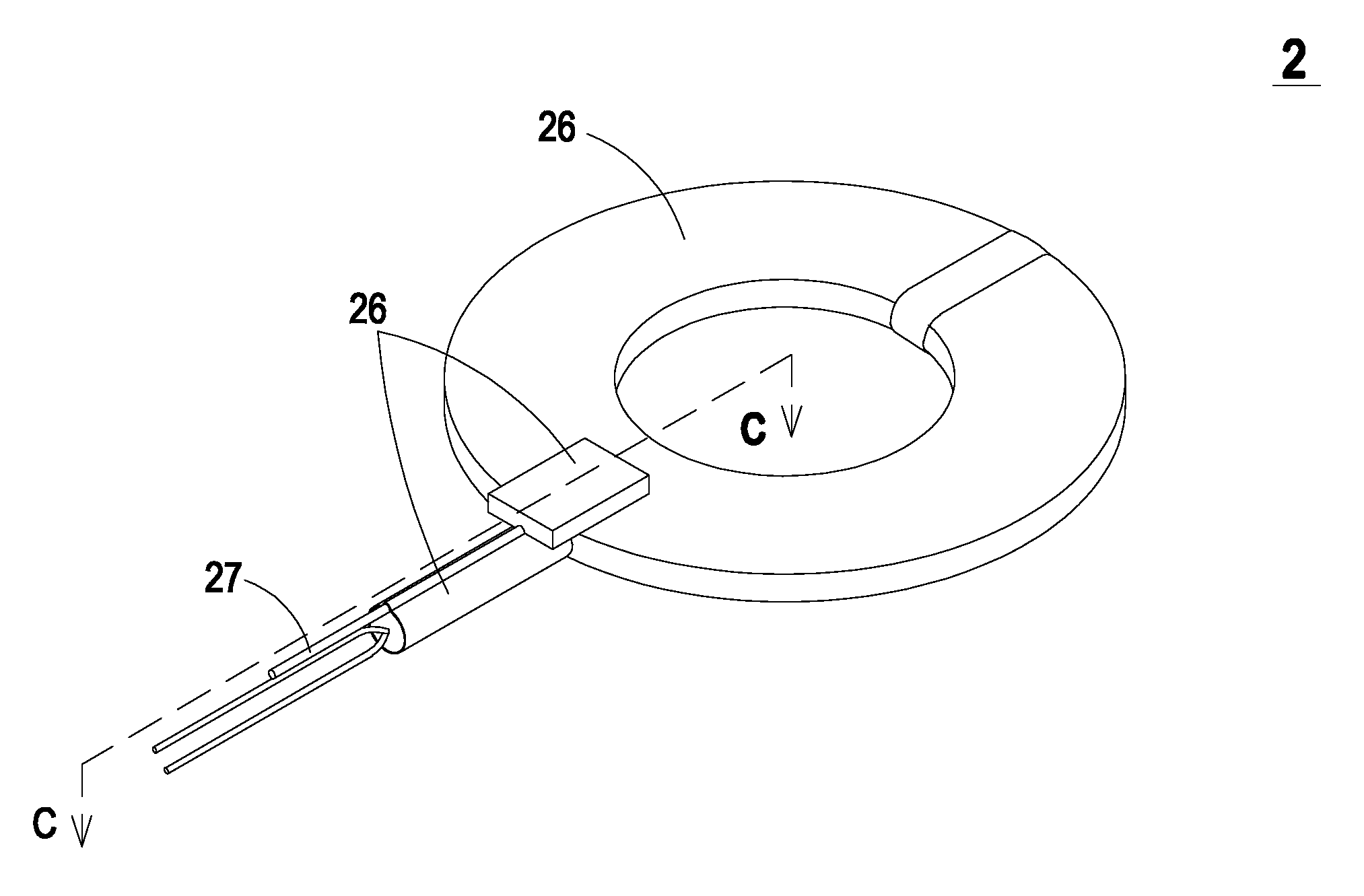
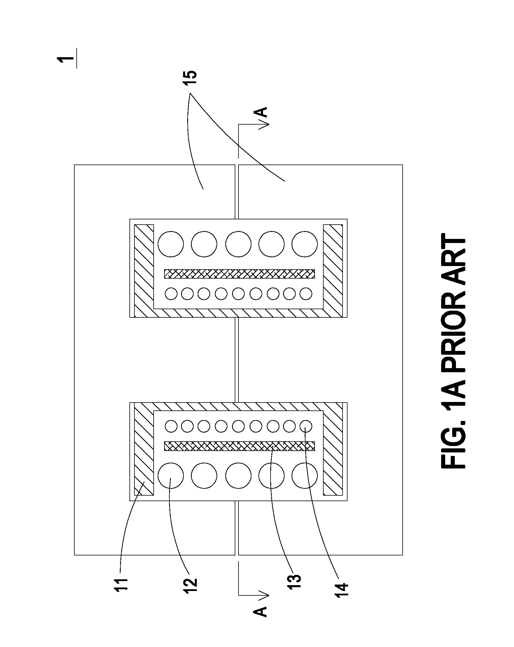
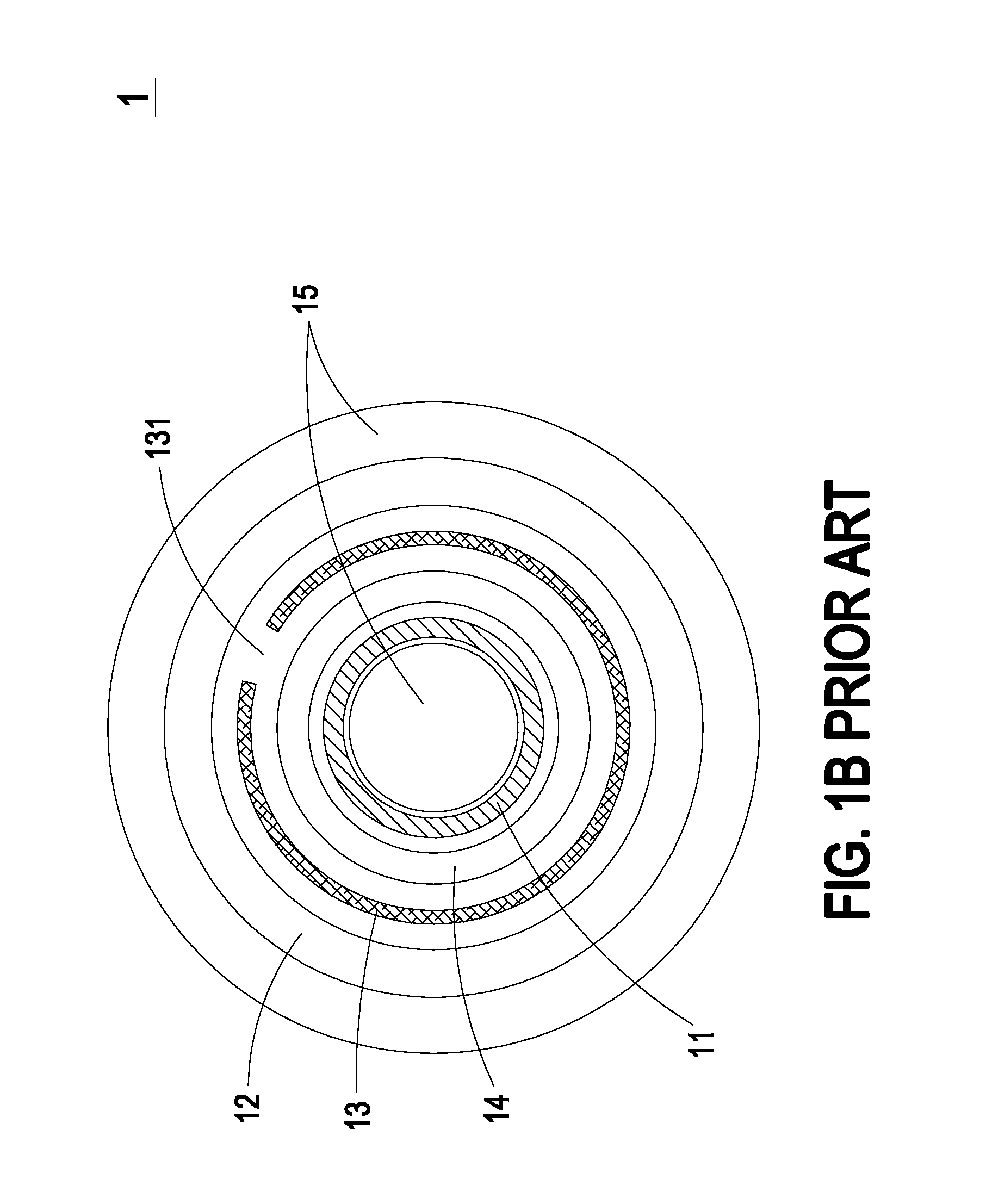
[0021]FIG. 2A is a schematic perspective view illustrating a coil assembly with a shielding function according to an embodiment of the present invention. FIG. 2B is a schematic cross-sectional view of the coil assembly shown in FIG. 2A and taken along the line BB. As shown in FIGS. 2A and 2B, the coil assembly 2 comprises at least one insulated wire 21 and an EMI shielding layer 22. The insulated wire 21 is wound into a winding coil part 23, which includes a first wire-outlet segment 21a and a second wire-outlet segment 21b. The winding coil part 23 includes a through-hole 24 in the center thereof. The EMI shielding layer 22 is f...


PUM

PropertyMeasurementUnit
thicknessaaaaaaaaaa
electromagnetic interferenceaaaaaaaaaa
shieldingaaaaaaaaaa

Abstract

A coil assembly includes at least one insulated wire and an electromagnetic interference shielding layer. The insulated wire is wound into a winding coil part. The winding coil part includes a first wire-outlet segment, a second wire-outlet segment and a central through-hole. The electromagnetic interference shielding layer is formed on the winding coil part for shielding the insulated wire. The electromagnetic interference shielding layer has lateral projection profile on the winding coil part. The electromagnetic interference shielding layer has a radial gap such that the electromagnetic interference shielding layer is a non-conducting loop.

Description

FIELD OF THE INVENTION[0001]The present invention relates to a coil assembly and a magnetic element, and more particularly to a coil assembly and a magnetic element with shielding functions.BACKGROUND OF THE INVENTION[0002]Nowadays, magnetic elements such as transformers and inductors are widely used in many electronic devices to generate induced magnetic fluxes. There are many methods for fabricating a magnetic element that is used in a switching power supply apparatus. According to a first method, a single-layered or three-layered insulated wire is wound around a magnetic core. According to a second method, after a coil pancake is produced by winding an insulated wire, the coil pancake is wound around a bobbin and then combined with a magnetic core. According to a third method, after an insulated wire is wound around a bobbin, the bobbin is combined with a magnetic core. Since the switching power supply apparatus has some switch elements, the magnetic element is readily suffered f...

Claims


Application Information

Patent Timeline
Patent Type & Authority Applications(United States)
IPC IPC(8): H01F17/00
CPCH01F27/2885
Inventor ZENG, JIAN-HONGHONG, SHOU-YUYE, NANYANG, WEIYING, JIAN-PING
Owner DELTA ELECTRONICS INC
Why Eureka
Try Eureka