Antenna alignment method and apparatus

a technology of antenna alignment and antenna axis, applied in the direction of electrical equipment, radio transmission, transmission, etc., can solve the problems of insatisfactory automatic alignment based on error correction, limited antenna alignment solution, and broken existing methods of antenna alignmen

Active Publication Date: 2010-12-02
SIKLU COMM
View PDF11 Cites 62 Cited by
  • Summary
  • Abstract
  • Description
  • Claims
  • Application Information

AI Technical Summary

Benefits of technology

[0029]In an embodiment, said transmitting unit is configured to transmit an indication to said second antenna to signal corresponding alignment steering from said second antenna, thereby to mutually align said antennas by said maximizing of said quality.

Problems solved by technology

In most of the cases the antenna alignment solution is limited to the scope of one antenna to be aligned.
Error correction is possible if the number of errors is below a threshold and not possible if the number of errors is above the threshold.
The automatic alignment based on error correction is not satisfactory when a narrow beam is being broadcast.
However the higher the frequency the narrower the pencil beam can be and existing methods of antenna alignment break down.

Method used


Image

  • Antenna alignment method and apparatus
  • Antenna alignment method and apparatus
  • Antenna alignment method and apparatus

Examples


Embodiment Construction

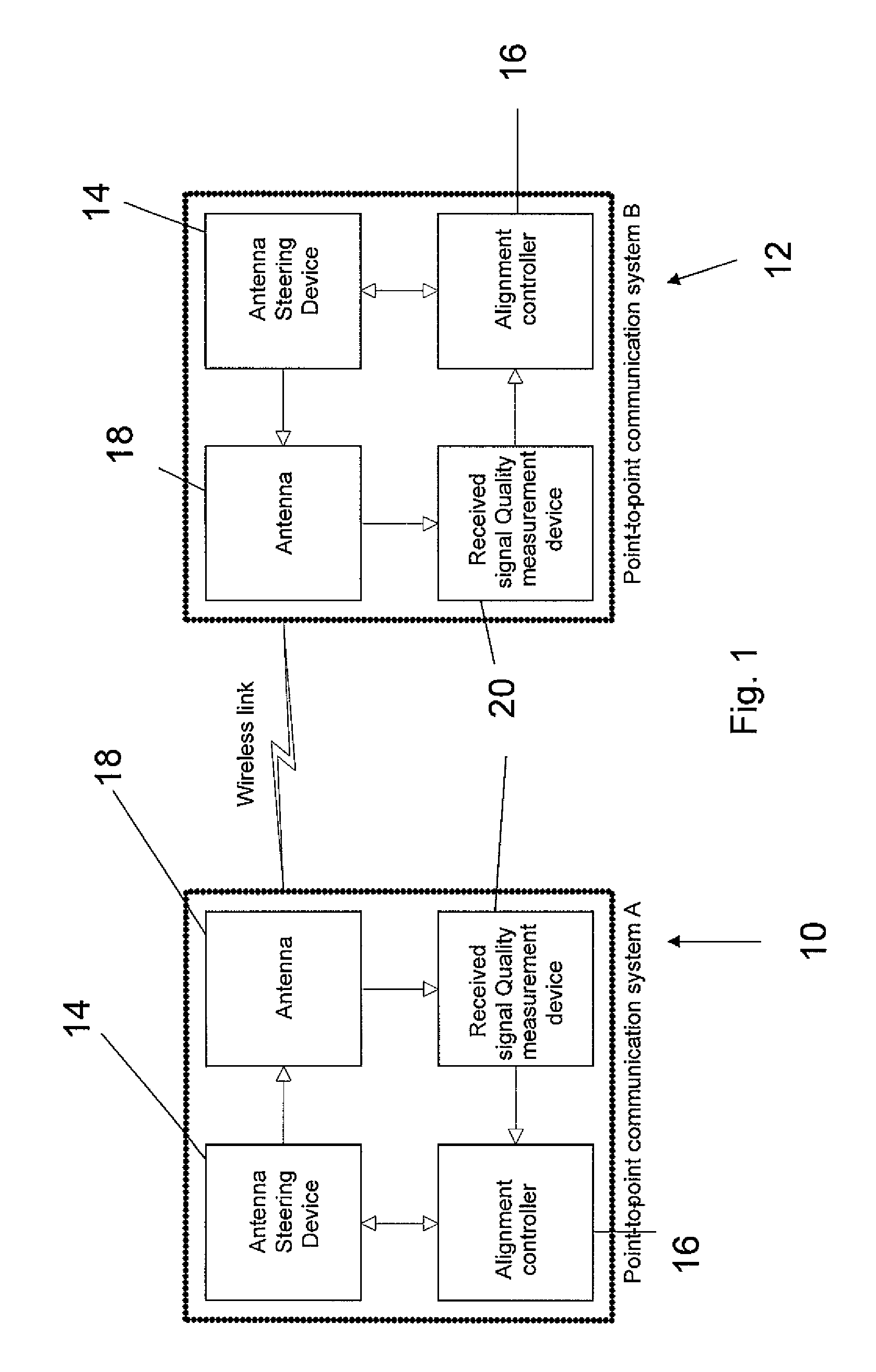
[0043]The present invention relates to a device, system and method for antenna alignment, and more particularly but not exclusively to a method of antenna alignment which is useful for the backhaul connections in a cellular telephone network. Generally, directional beam antennas and pencil beam antennas are used for such connections. If millimeter wave bands are used then the directional antennas are likely to be pencil beam antennas. Pencil beams are particularly applicable to E-band frequencies.

[0044]The present embodiments may provide a device, system and method that enables optimal and efficient alignment of a pair of antennas used in a point-to-point terrestrial wireless communication link, in particular where the links are narrow beam links. The present embodiments may be used either in an open-loop fashion, where an external entity is used to steer the antenna beam, or in closed-loop mode where the system automatically steers the beam without any external entity.

[0045]The pre...


PUM


Abstract

A method of automatic alignment of two directional beams having a known path attenuation, and an antenna gain pattern, for mutual transmission, comprises: determining a beam width between two angles of minimal detectable connection on either side of a beam maximum; then mapping points onto a scan field in a regular pattern, the pattern based on the beam width, such that a beam with the determined beam width is detected once if the beam is in the scan field at all; scanning the first antenna over the mapped scan points; and for each point allowing the second antenna to scan over all of its own set of mapped scan points, thereby providing a coarse alignment of the two antennas to achieve at least a minimal mutual connection. The coarse alignment may be followed by a fine alignment to maximize the signal.

Description

FIELD AND BACKGROUND OF THE INVENTION[0001]The present invention relates to a device and method for antenna alignment, and more particularly to a method of antenna alignment which is useful inter alia for the backhaul connections in a cellular telephone network.[0002]There are many methods used for antenna alignment and for an associated alignment mechanism. Some of them rely on geographical data, others rely on received signal level measurements and some incorporate motors in order to align the antenna. In most of the cases the antenna alignment solution is limited to the scope of one antenna to be aligned.[0003]A relatively early example of automatic antenna alignment is illustrated by U.S. Pat. No. 5,551,058 assigned to Thomson Consumer Electronics Inc. Here a satellite receiver is aligned to a satellite. The receiver, which is for digitally encoded television signals, includes apparatus for aligning the receiving antenna to the satellite. The alignment apparatus is responsive to...

Claims


Application Information

Patent Timeline
Patent Type & Authority Applications(United States)
IPC IPC(8): H01Q3/00
CPCH01Q1/1257
Inventor LEIBA, YIGALSCHWARZ, BARUCHDAYAN, ELADKIRSHENBAUM, IZHAK
Owner SIKLU COMM
Why Eureka
Try Eureka