Very high power connector

a connector, very high technology, applied in the direction of coupling device connection, electrical apparatus, two-part coupling device, etc., can solve the problems of bulky, increase in the diameter of the connector, and reduce the cutoff frequency of the connector, so as to reduce the risk of breakdown associated with the multi-pactor

Active Publication Date: 2010-12-02
RADIALL SA
View PDF11 Cites 10 Cited by
  • Summary
  • Abstract
  • Description
  • Claims
  • Application Information

AI Technical Summary

Benefits of technology

[0063]A connector presenting insulation in two portions with an interface having at least a fraction that is not colinear with the radial electric field lines within the coaxial connector serves to avoid creating avalanches of electrons in a vacuum and serves to avoid charge accumulating at the interfaces between the portions of the insulation, as explained above.
[0064]A connector presenting insulation having a portion that is configured to exert a holding action on the insulation of the coaxial cable on which the connector is mounted makes it possible, because of this holding action, to avoid creating a gap between the insulation of the coaxial connector and the insulation of the coaxial cable, in particular as a result of the insulation of the cable backing off under the effect of thermal expansion.
[0065]With a connector presenting both characteristics described above, the risks of breakdown associated with the multipactor effect are reduced significantly.

Problems solved by technology

Nevertheless, this increase in the diameter of the central contact leads to an increase in the diameter of the connector, and that can lead to problems in terms of bulk and can lower the cutoff frequency of the connector.
Such a solution does not improve the transfer of heat from the central contact to the body of the coaxial connector.
Such a solution is not entirely satisfactory for applications in vacuum conditions.
Furthermore, it does not improve the transfer of heat from the central contact towards the body of the coaxial connector.
In addition, in such vacuum conditions, there is a non-negligible risk of the connector being subjected to the multipactor effect, which corresponds to a discharge phenomenon that occurs in microwave or radiofrequency components.
In particular as a result of using polyethylene and polytetrafluoroethylene (PTFE) for making the portions of the insulation, such a connector is not suitable for dissipating high powers at altitude, and more particularly under vacuum conditions.

Method used


Image

  • Very high power connector
  • Very high power connector
  • Very high power connector

Examples


Embodiment Construction

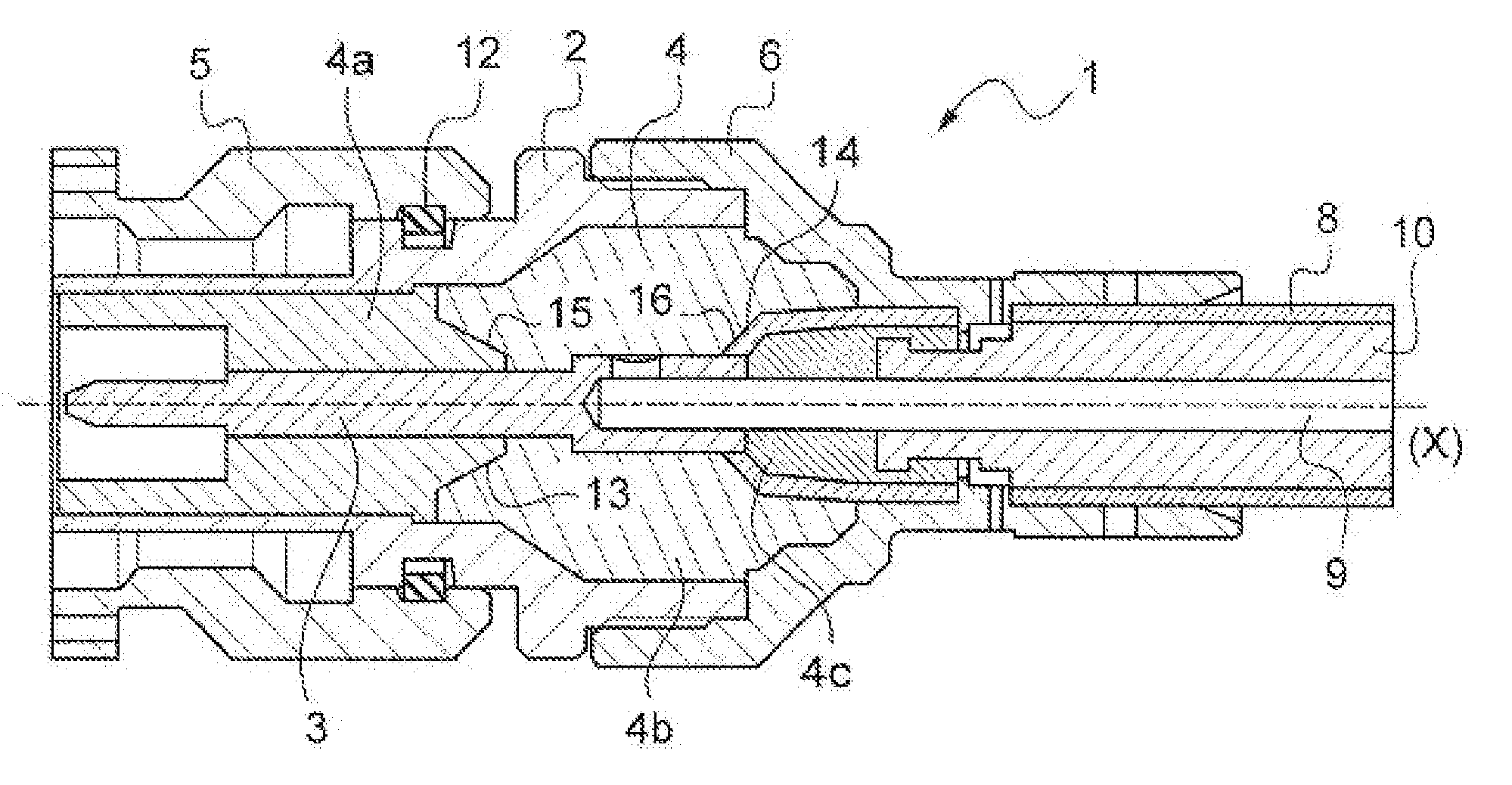
[0078]FIG. 1 shows an example of a coaxial connector of axis X, e.g. a connector of the TNC type, given overall reference 1. This coaxial connector 1 in the example describes comprises a body 2 made as a single piece, and a central contact 3 mounted in the body 2 with interposition of insulation 4. A passage 7 of cylindrical shape is formed in the insulation 4 to receive the central contact 3, which has an outside shape that is substantially cylindrical in the example shown.

[0079]In the example described, the coaxial connector 1 also includes a cap 5 mounted on the front of the body 2, and a sleeve 6 mounted on the rear of the body 2. In the example described, the cap 5 defines a front portion of the connector 1 suitable for coupling to a complementary coaxial connector, while the sleeve 6 defines a rear portion of the connector 1 for mounting on a coaxial cable 8.

[0080]As can be seen in FIG. 1, the coaxial cable 8 has a central contact 9 and insulation 10 surrounding the central co...


PUM


Abstract

The present invention relates to a coaxial connector comprising:
    • a body; and
    • a central contact mounted in the body with interposition of insulation;
    • wherein the insulation comprises at least two distinct portions:
    • a) that are separated by an interface presenting at least a fraction that extends obliquely relative to the axis of the connector; and/or
    • b) that are made of different dielectric materials;
    • the connector being configured to withstand breakdown phenomena at altitude, in particular under vacuum conditions.

Description

FIELD OF THE INVENTION[0001]The present invention relates to a coaxial connector.[0002]The invention applies more particularly to a coaxial connector for applications in the field of space, where such a connector is advantageously capable of withstanding high powers at altitude, and more particularly under vacuum conditions. The term “at altitude” should be understood as meaning an altitude greater than 30,000 feet. In the meaning of the invention, vacuum conditions are those of at least a primary vacuum, i.e. 105 pascals (Pa), down to the conditions of the vacuum in space, i.e. 1.33×10⁻⁸ Pa. The term “high powers” means powers of about 400 watts (W) at frequencies of 1 or 2 gigahertz (GHz), of 300 W at frequencies of 7 GHz, and of a few hundreds of watts at 18 GHz. The power to which the connector is subjected may for example be greater than 100 W.BACKGROUND OF THE INVENTION[0003]The higher the frequency of the signal, the larger the amount of heat that needs to be dissipated. In o...

Claims


Application Information

Patent Timeline
Patent Type & Authority Applications(United States)
IPC IPC(8): H01R9/05
CPCH01R13/533H01R24/40H01R2103/00
Inventor MANA, EDITHFOND, EMILIE
Owner RADIALL SA
Why Eureka
Try Eureka