Disk array, and disk array control method and program

a control method and disk array technology, applied in the field of disk arrays and control methods of disk arrays, can solve the problems of reducing the parallel operation increasing the loss, and becoming difficult or disadvantageous in terms of bit unit price acquisition, so as to achieve the capacity efficient rate sacrificing the high speed performance of the disk array, and improving the different capacity

Inactive Publication Date: 2010-12-02
HITACHI LTD
View PDF1 Cites 40 Cited by
  • Summary
  • Abstract
  • Description
  • Claims
  • Application Information

AI Technical Summary

Benefits of technology

[0021]According to the present invention, the capacity efficient rate of a disk array configured by attaching storage devices (disk storages) having a different capacity can be improved without sacrificing the high speed performance of the disk array.

Problems solved by technology

On the other hand, the increase in the capacity of hard disk drive makes it possible to secure the increasing digital data, but increases the loss in the case of the crash of hard disk drive.
However, in many cases, due to the remarkable increase in the disk capacity in recent years, it has become difficult or a disadvantageous in terms of bit unit price to acquire, at the time of disk crash, the disk having the same capacity as the capacity used when the system is configured.
However, even in any of the system according to JP Patent Publication (Kokai) No. 2002-99391 and JP Patent Publication (Kokai) No. 08-63298, there is a problem that as compared with the RAID, the parallel operation rate of the disks is lowered and thereby the performance is deteriorated.
Further, in the technique described in JP Patent Publication (Kokai) No. 08-63298, all the disks are operated in parallel as long as the disk having the smallest capacity can store data, but there is a problem that the parallel operation rate of the disks is gradually lowered as the amount of stored data is increased.
Further, in the technique described in any one of JP Patent Publication (Kokai) No. 2002-99391 and JP Patent Publication (Kokai) No. 08-63298, the stripe structure length set in the respective disks is fixed, which is also a cause of the lowering of the speed.
This is because a large capacity hard disk drive generally used as a storage device in the RAID has a feature that a disk having a larger capacity can perform read and write operations at higher speed, and hence a disk having a low read and write speed becomes an obstacle in read and write operations of fixed data length (chunk structure), so as to prevent the speed performance of the large capacity disk from being exhibited.

Method used


Image

  • Disk array, and disk array control method and program
  • Disk array, and disk array control method and program
  • Disk array, and disk array control method and program

Examples


first embodiment

(1) First Embodiment

[0043]A first embodiment relates to a disk array using RAID 0.

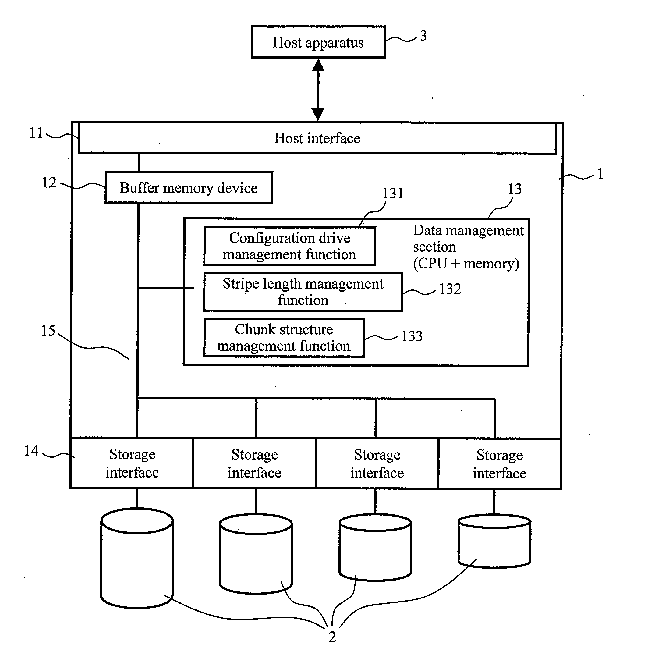
[0044]FIG. 1 is a diagram showing a schematic configuration of a disk array according to a first embodiment of the present invention. As shown in FIG. 1, a disk array 1 includes: a host interface 11 which performs communication with a host apparatus 3; a buffer memory device (buffer memory including cache memory) 12 which temporarily stores data; a data management section 13 which performs data management in the disk array; a plurality of storage interfaces 14 (four in the figure) which are used to attach storage devices 2; and a communication bus 15 which connects these components to each other and which transmits data, an instruction, and the like.

[0045]The host interface 11 may be a communication interface having an effective transfer rate in a range of about 500 Mbps, such as the interfaces of Universal Serial Bus and of IEEE 1394, but is preferably a communication interface having a transfer rate ...

second embodiment

(2) Second Embodiment

[0077]The first embodiment does not have resistance against a crash of the storage device 2. Thus, in the present embodiment, RAID 5 is used to realize the crash resistance in the disk array 1.

[0078]FIG. 7 is a diagram showing a schematic configuration of a disk array according to a second embodiment of the present invention. The disk array 1 includes: the host interface 11 which performs communication with the host apparatus 3; the buffer memory device (buffer memory including cache memory) 12 which temporarily stores data; the data management section 13 which performs management of data in the disk array 1; the plurality of storage interfaces 14 (four in the figure) which are used to attach the storage devices 2; and the communication bus 15 which connects these components to each other and which transmits data, an instruction, and the like.

[0079]A parity management function 134 has a function of generating, even when any one of the stripe structures 25 config...


PUM


Abstract

A data management section manages source data from a host apparatus by dividing the source data into a plurality of stripe structure data, and distributes and stores the plurality of stripe structure data in a plurality of storage devices having different capacity. Then, the data management section performs control for determining the length of the stripe structure data according to the capacity of each of the plurality of storage devices, and stores the stripe structure data of the same length in each of the storage devices. Further, the data management section manages, as a chunk structure, a data set configured by each one of the stripe structure data respectively stored in the plurality of storage devices. At this time, the source data is configured by a set of the chunk structures. The above contents are the same in RAID 0 and RAID 5.

Description

CLAIM OF PRIORITY[0001]The present application claims priority from Japanese patent application JP 2009-133176 filed on Jun. 2, 2009, the content of which is hereby incorporated by reference into this application.BACKGROUND OF THE INVENTION[0002]1. Field of the Invention[0003]The present invention relates to a disk array, and a control method and program of the disk array. The present invention relates to, for example, a disk array which configures a virtual storage by a plurality of storage devices.[0004]2. Background Art[0005]In recent years, the amount of digital data and the capacity of hard disk drive tend to be increased. The increase of digital data increases the importance of data redundancy. On the other hand, the increase in the capacity of hard disk drive makes it possible to secure the increasing digital data, but increases the loss in the case of the crash of hard disk drive.[0006]In such situations, a storage device of terabyte order has come to be installed even in th...

Claims


Application Information

Patent Timeline
Patent Type & Authority Applications(United States)
IPC IPC(8): G06F12/00
CPCG06F2211/1059G06F11/1076
Inventor SHIONOYA, TOMOTAKA
Owner HITACHI LTD
Why Eureka
Try Eureka