Electric motor

Active Publication Date: 2010-12-09
MITSUBA CORP
View PDF6 Cites 10 Cited by
  • Summary
  • Abstract
  • Description
  • Claims
  • Application Information

AI Technical Summary

Benefits of technology

[0019]According to the present invention, since two coil groups of three-phase concentrated windings can be connected in parallel to a segment of a commutator, the number of parallel circuits can be increased to 4. For this reason, as compared with a case where the number of parallel circuits is two, it is possible to utilize a winding with a thin line diameter. As the line diameter is thin, it is possible to easily perform the winding task on the winding.
[0020]In addition, if A is a natural number of 2 or more, the number of the magnetic poles is P, the number of the slots is Sr, and the number of the segments is Se, in order to satisfy P=4A, Sr=6A, and Se=12A, the number P of the magnetic poles, the number Sr of the slots and the number Se of the segments are set, and thus the number Se of the segments is twice the number Sr of the slots. For this reason, as compared with the related art in which the number of the segments is set to be equal to the number of the slots, it is possible to decrease the voltage between the segments. Therefore, it is possible to suppress the discharge from being produced between the segment and the brush which comes into slide contact with the segment.
[0021]In addition, in the case in which the number Se of the segments is twice the number Sr of the slots, the coil of each phase is configured of a first coil wound in a forward direction, and a second coil wound in a reverse direction, so that the center of rectification for every phase can be set to the center between the adjacent segments. For this reason, the center of rectification for each phase can be easily recognized, and thus each of the brushes is installed such that the center of rectification and the center of the brush coincide, thereby improving the rectifying characteristics and thus improving the characteristics of the electric motor.

Problems solved by technology

However, in the above-described related art, in the case where the winding is wound in a three-phase concentrated winding manner, the number of the parallel circuits is two, irrespective of the number of the slots, so that there is a limit in rendering the diameter of the winding thin.
For this reason, since it is necessary to render the line diameter of the winding thick, it is difficult to perform the winding task.

Method used


Image

  • Electric motor
  • Electric motor
  • Electric motor

Examples


first embodiment

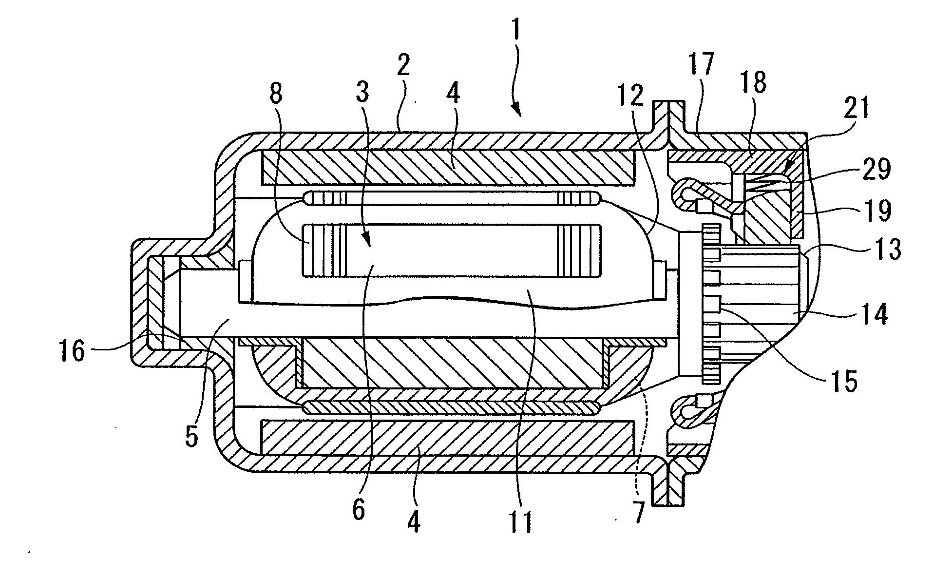
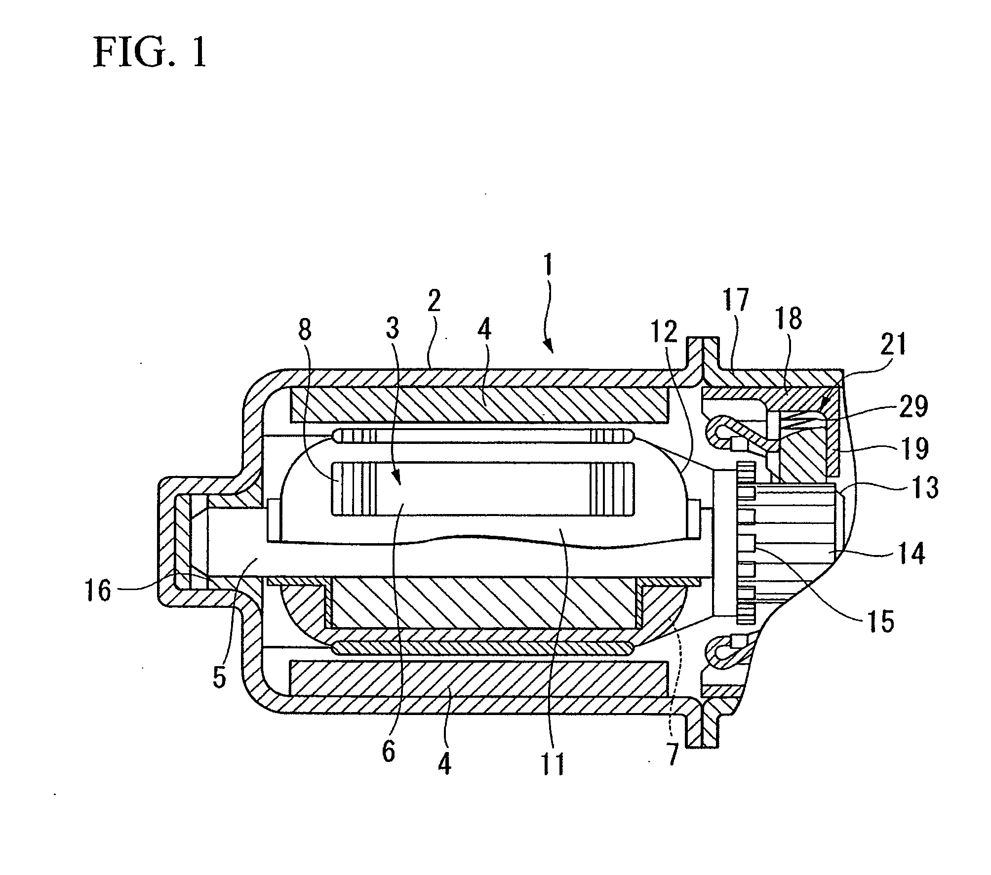
[0030]Next, the present invention will be described with reference to FIGS. 1 to 4.

[0031]As shown in FIGS. 1 and 2, an electric motor 1 is a driving source of electric components (e.g., a radiator fan) mounted on a vehicle, and includes a cylindrical yoke 2 having a bottom, and an armature 3 rotatably disposed in the yoke 2. A plurality (8 poles in the first embodiment) of permanent magnets 4 are fixed to an inner circumference of the yoke 2 at equal intervals in a circumferential direction.

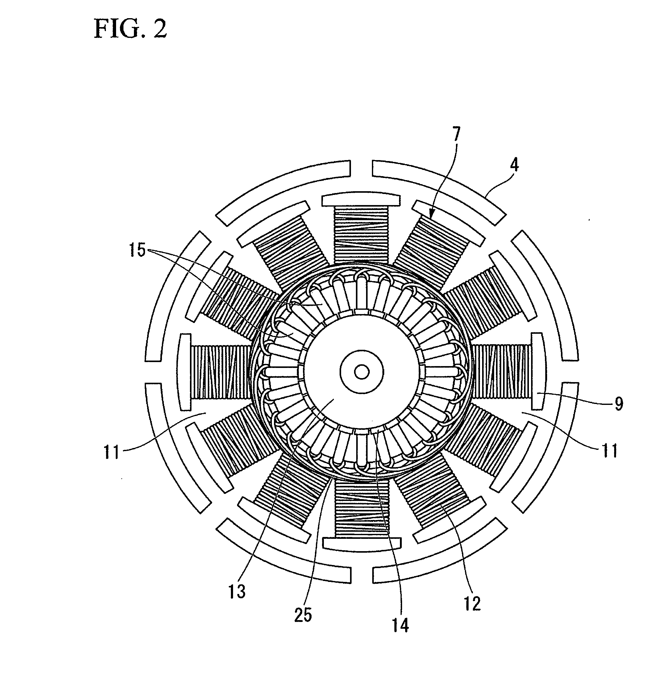
[0032]The armature 3 includes an armature core 6 fixed to a rotational shaft 5, an armature coil 7 wound around the armature core 6, and a commutator 13 disposed at one end portion of the armature core 6. The armature core 6 includes a plurality of ring-shaped metal plates 8 which are layered in an axial direction. The metal plate 8 is provided on an outer circumferential portion thereof with a plurality (12 in the first embodiment) of T-shaped teeth 9 (refer to FIG. 2) radially disposed at equal...

second embodiment

[0067]Next, the present invention will be described with reference to FIG. 4.

[0068]FIG. 4 is a developed view of an armature 3 showing a winding state of an armature coil 7, and the basic configuration is substantially identical to that of the above-described first embodiment. Therefore, in FIG. 4, the same members and parts as those of FIG. 3 are denoted by the same reference numerals, and detailed descriptions thereof will be omitted (hereinafter, identical to the embodiments below).

[0069]In addition, in the embodiments below, the basic configuration of the electric motor 1, which, for example, includes a yoke 2 having a permanent magnet 4, and an armature 3 rotatably disposed in the yoke 2, is identical to that of the above-described first embodiment.

[0070]Here, in the second embodiment, the winding 12 is wound in series around each of the teeth 9 of three phases (U, V and W phases), which are at intervals of 3 teeth, in a concentrated winding manner, and two coil groups 71 and 7...

third embodiment

[0075]Next, the present invention will be described with reference to FIG. 5.

[0076]In the third embodiment, an electric motor 51 has an 8-pole, 12-slot and 12-segment structure, in which the number of poles of permanent magnets 4 is 8, the number of slots 11 is 12, and the number of segments 14 is 12. That is, if the number of the magnetic poles of the permanent magnets 4 is P, the number of the slots 11 is Sr, the number of the segments 14 is Se, and A is a natural number of 2 or more, in order to satisfy

P=4A, Sr=6A, and Se=6A,

[0077]the number P of the magnetic poles, the number Sr of the slots and the number Se of the segments are set, and in the third embodiment, A=2 (even number of 2 or more), and,

P=4A=4×2=8,Sr=6A=6×2=12,Se=6A=6×2=12.

[0078]In addition, the segments 14 having the same potential are short-circuited by a connection line 25. That is, the segments 14 at intervals of 2 segments (e.g., a first segment 14a and a fourth segment 14c) are short-circuited by the connection ...


PUM


Abstract

The windings (12) wound around each of the teeth (9) form two coil groups (71, 72) of three-phase concentrated windings which are disposed point-symmetrically to each other with respect to the rotational shaft. Each of the coil groups (71, 72) includes a first coil (33), in which the windings (12) are wound around the teeth in a forward direction, and a second coil (34), in which the windings (12) are wound around the teeth in a reverse direction. When each of the teeth (9) is allocated with a U phase, a V phase, and a W phase in this order in a circumferential direction so that the first coil (33) wound for each phase is set to be coils of the U phase, the V phase, and the W phase, and the second coil (34) wound for each phase is set to be coils of the −U phase, the −V phase, and the −W phase, the coils of the U, −W, V, −U, W and −V phases are electrically connected between the adjacent segments (14) in this order.

Description

TECHNICAL FIELD[0001]The present invention relates to an electric motor which is mounted on a vehicle or the like.[0002]This application claims priority to and the benefit of Japanese Patent Applications No. 2008-021660 filed on Jan. 31, 2008, the disclosure of which is incorporated herein by reference.BACKGROUND ART[0003]Generally, a three-phase electric motor with a brush which is mounted on a vehicle or the like includes a cylindrical yoke having permanent magnets attached to its inner circumference, and an armature wound with an armature coil and rotatably disposed in the yoke. The armature includes an armature core externally fitted and fixed to a rotational shaft. The armature core is provided with a plurality of teeth in a radial direction, and elongated slots are formed between the teeth in an axial direction. A winding is wound around each of the teeth to form a coil of a three-phase (U-phase, V-phase and W-phase) structure.[0004]Coils are in electrical communication with a...

Claims


Application Information

Patent Timeline
IPC IPC(8): H02K3/28
CPCH02K23/36
Inventor KAWASHIMA, YOSHICHIKASHIODA, NAOKI
Owner MITSUBA CORP
Why Eureka
Try Eureka