Sensor Assembly

Inactive Publication Date: 2010-12-09
SCHLUMBERGER TECH CORP
View PDF54 Cites 23 Cited by
  • Summary
  • Abstract
  • Description
  • Claims
  • Application Information

AI Technical Summary

Problems solved by technology

Lastly, a fiber optic line is coupled to the device such that light passing therethrough may b

Method used


Image

  • Sensor Assembly
  • Sensor Assembly
  • Sensor Assembly

Examples


Embodiment Construction

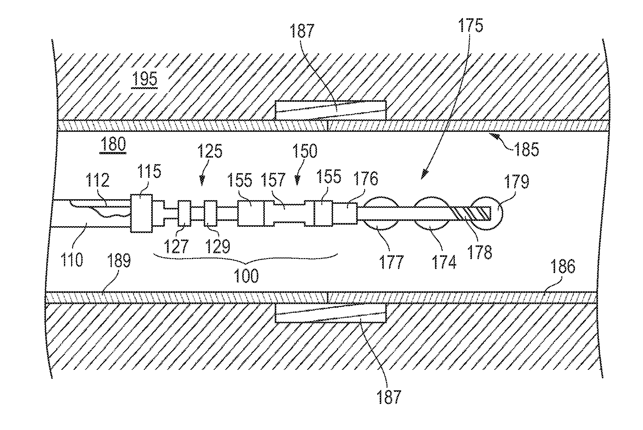
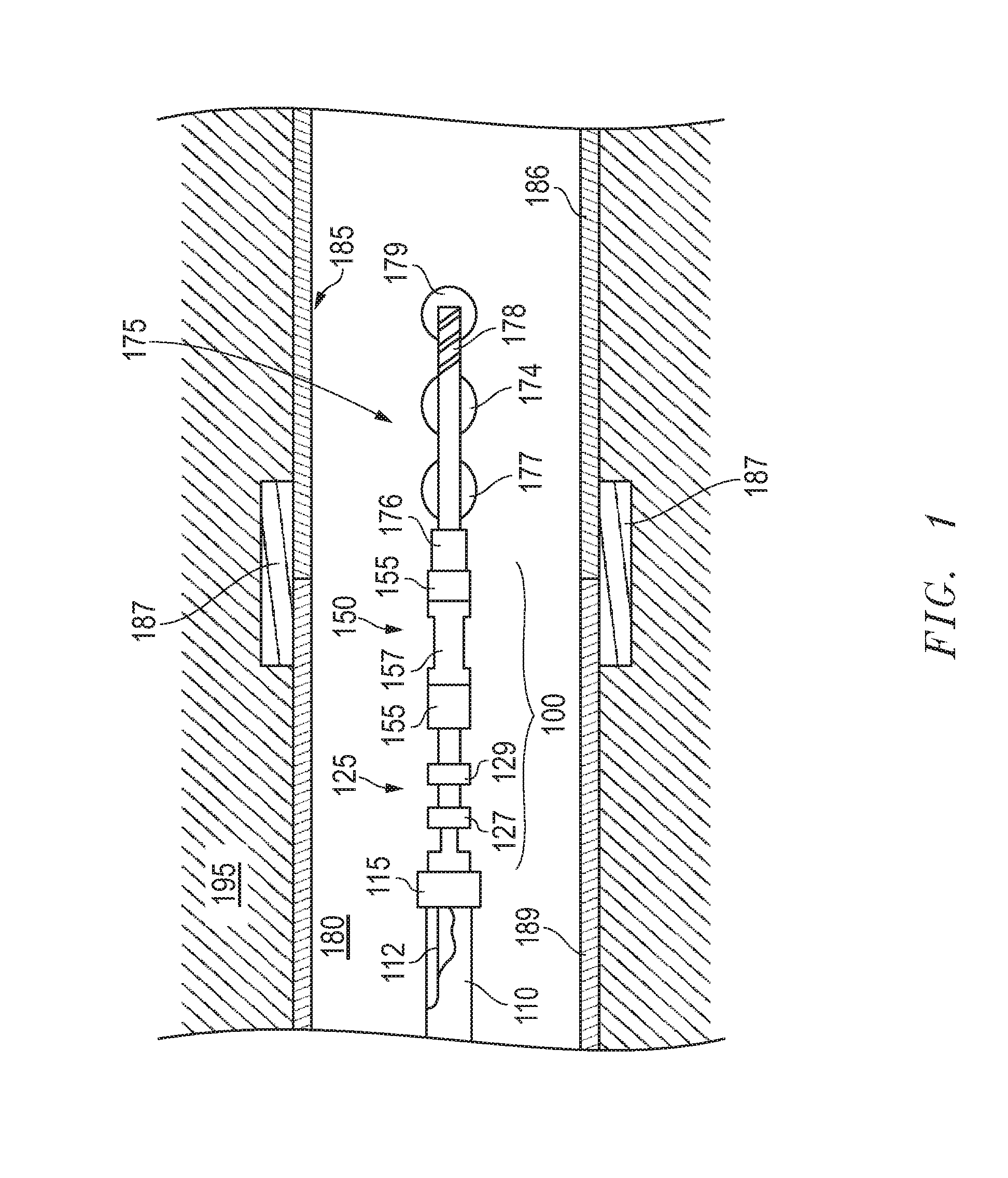
[0015]Embodiments are described with reference to certain sensor assemblies for detection of downhole casing collars in a hydrocarbon well. As such, embodiments are generally depicted as casing collar locator assemblies for establishing accurate positioning of associated downhole tools. However, a variety of configurations may be employed. For example, sensor assembly embodiments as described herein may be employed for detection of wall features in a variety of wells, pipes, or other appropriate conduits. Regardless, embodiments described herein are employed that utilize a dimensionally alterable voltage responsive device. As detailed herein, where appropriately configured, such a piezo-like device may obviate the need for coupling a separate dedicated power source to the sensor assembly. Thus, a significant amount of footspace may be saved while at the same time improving the overall longevity and reliability of the assembly.

[0016]Referring now to FIG. 1, downhole equipment is show...


PUM


Abstract

An assembly for passive detection of features at known locations of a conduit. The assembly is a sensor assembly particularly well suited for detection of casing collars at known locations of cased wells, such as segmented hydrocarbon wells. Thus, the assembly is able to provide real time positioning information relative to any tool coupled thereto which is being advanced in the well pursuant to a well application. Given that the detection takes place in a passive manner via the combination of a magneto-responsive sensor and voltage responsive device, no separate dedicated power source or additional electronics are required.

Description

CROSS REFERENCE TO RELATED APPLICATION[0001]This Patent Document claims priority under 35 U.S.C. §119(e) to U.S. Provisional Application Ser. No. 61 / 184,875 entitled High Sensitivity Optical Casing Collar Locator, filed on Jun. 8, 2009, and incorporated herein by reference in its entirety.FIELD[0002]Embodiments described relate to a sensor and techniques for establishing and monitoring a position of a tool through a conduit. In particular, techniques are described that minimize the amount of footspace that may be required by the sensor in acquiring and transmitting locating information over a fiber optic line.BACKGROUND[0003]Exploring, drilling and completing hydrocarbon and other wells are generally complicated, time consuming and ultimately very expensive endeavors. In recognition of these expenses, added emphasis has been placed on well logging, profiling and monitoring of well conditions. Over the years, the detecting and monitoring of well conditions has become a more sophistic...

Claims


Application Information

Patent Timeline
IPC IPC(8): E21B47/16G01V1/00
CPCE21B47/123E21B47/0905E21B47/092E21B47/135
Inventor BRADY, DOMINIC
Owner SCHLUMBERGER TECH CORP
Why Eureka
Try Eureka