Method of moulding a charge

a charge and charge technology, applied in the field of charge moulding, to achieve the effect of reducing wrinkles and superior forming results

Active Publication Date: 2010-12-09
AIRBUS OPERATIONS LTD
View PDF20 Cites 12 Cited by
  • Summary
  • Abstract
  • Description
  • Claims
  • Application Information

AI Technical Summary

Benefits of technology

[0015]It has been found that by making the diaphragm relatively stiff in the plane of the diaphragm, then the pressure is concentrated in any high curvature regions of the male tool, which is desirable from a debulking perspective. Also, it has been found that a superior forming result, with fewer wrinkles, is obtained by using such a relatively stiff diaphragm.

Problems solved by technology

This can become a significant problem when either:a) the part is of a significant thickness (typically>10 mm) and is at least partly non-planar; orb) the part incorporates padup areas a lot thicker than that of the surrounding material.

Method used


Image

  • Method of moulding a charge
  • Method of moulding a charge
  • Method of moulding a charge

Examples


Embodiment Construction

)

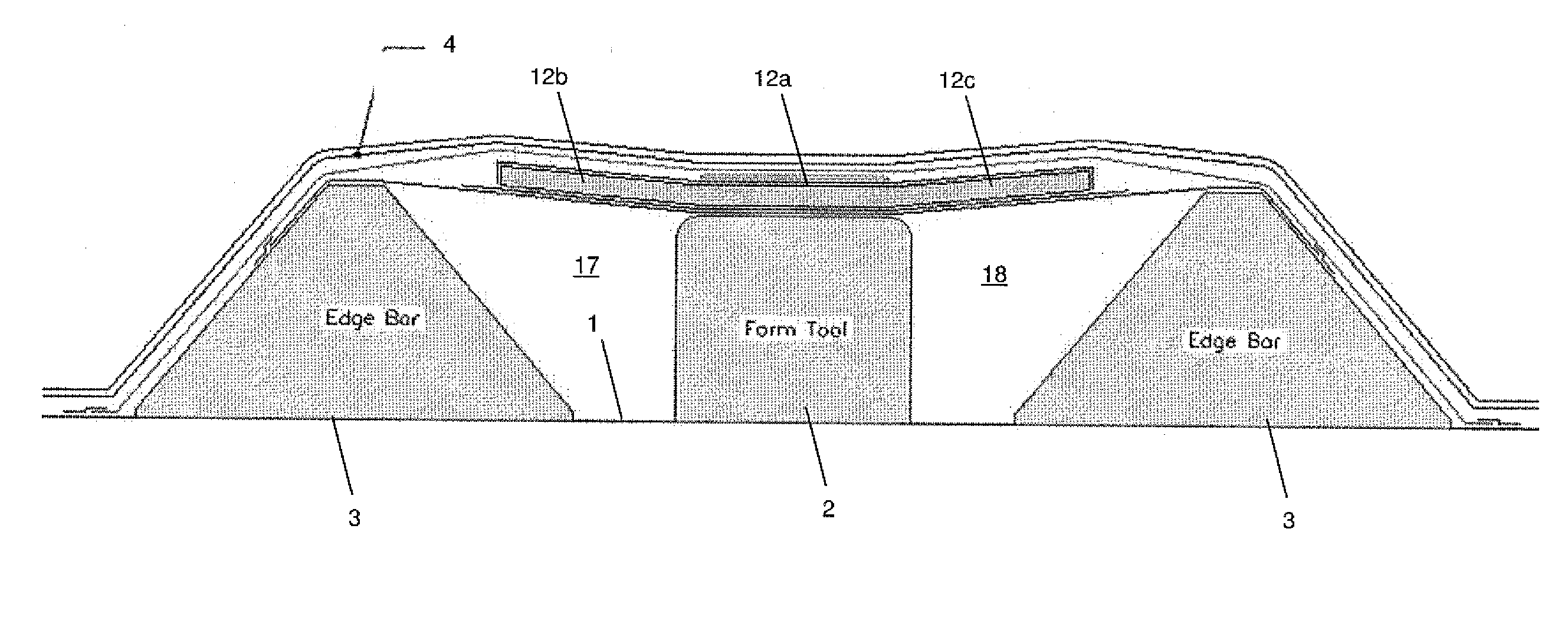
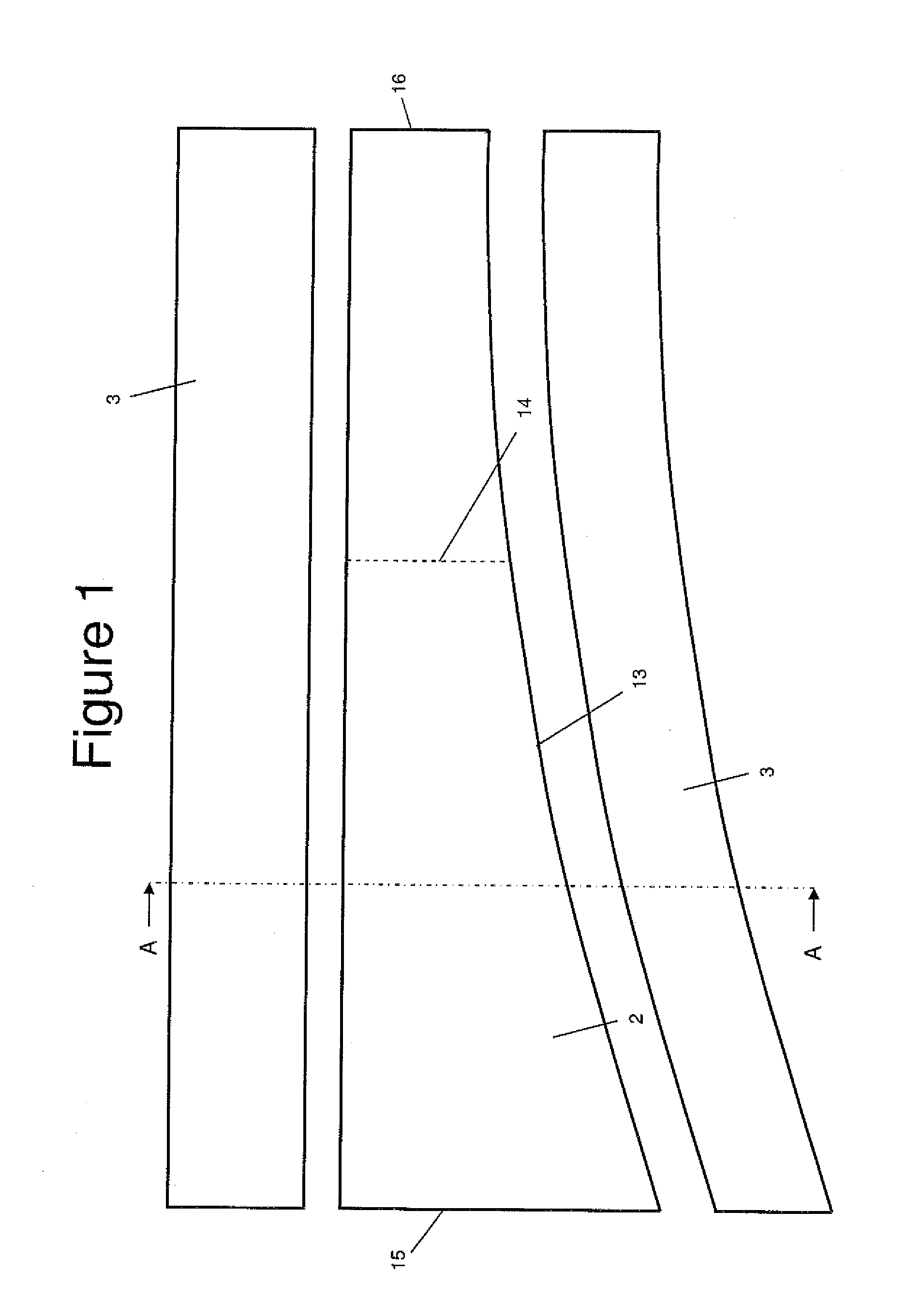
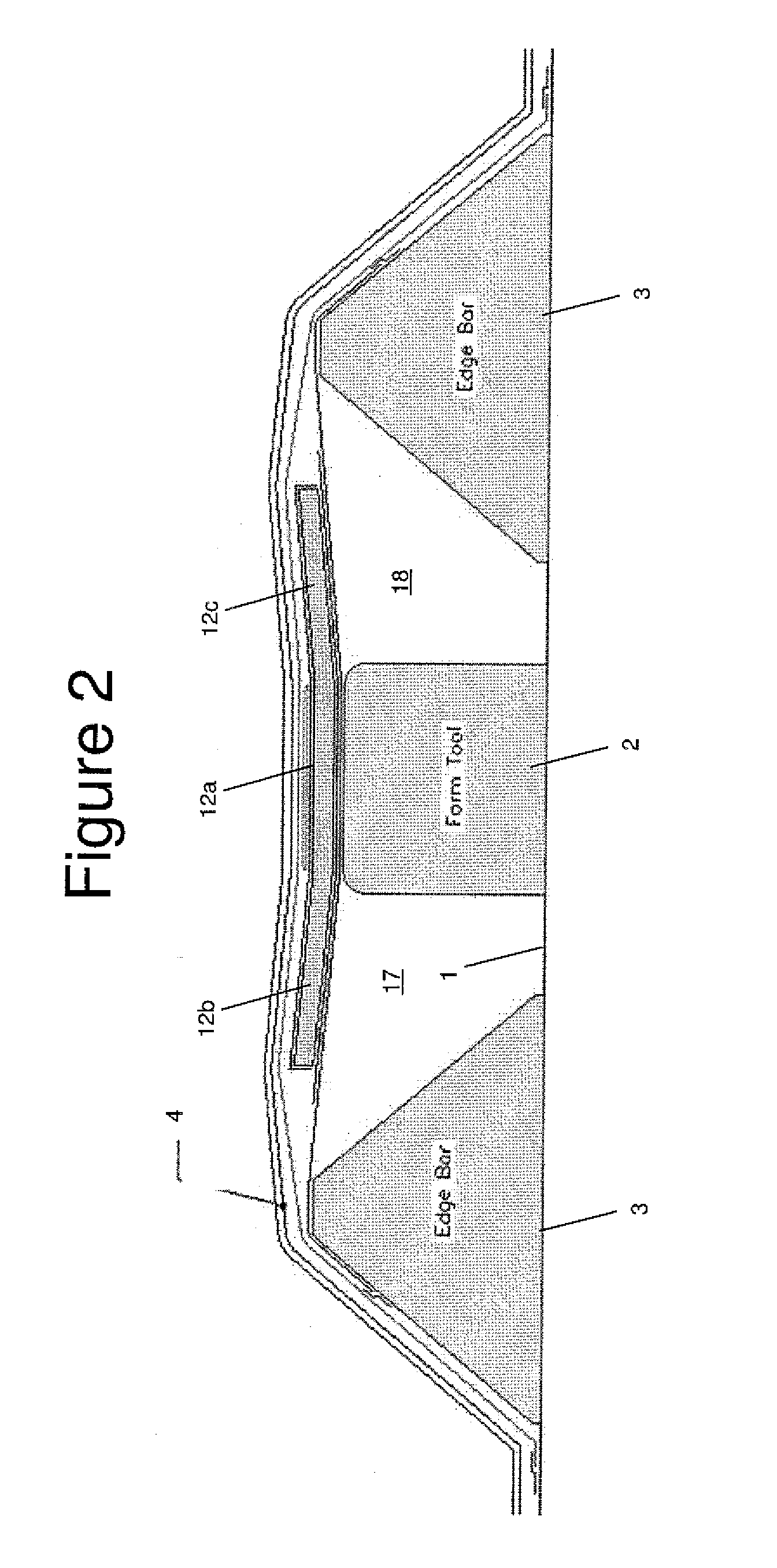
[0030]FIG. 1 is a plan view of a male moulding and debulking tool 2 and a pair of edge bars 3 which are used to form a C-section aircraft spar. FIG. 2 is a sectional view taken along line A-A in FIG. 1. As shown in FIG. 2, the tool 2 and edge bars 3 are mounted on a table 1.

[0031]In a first step, a planar sheet of composite prepreg is formed either by a tape-laying or other automated machine on a planar table (not shown). A planar prepreg charge 12 with the desired shape is then cut from the planar sheet. It will be appreciated that the prepreg charge 12 may be formed from a variety of suitable composite materials. In a preferred embodiment the charge is formed from an epoxy resin reinforced by uniaxial carbon fibres, such as T700 / M21 provided by Hexcel (www.hexcel.com).

[0032]Referring to FIG. 3, a flexible support membrane 8 of Vacfilm 430 is draped over the tool 2 and edge bars 3, and secured to the edge bars 3 by strips of tape 7. Vacfilm 430 is a high stretch elastomeric baggin...


PUM

PropertyMeasurementUnit
elongationaaaaaaaaaa

Abstract

A method of moulding a charge (12) during the manufacture of a composite part. The method comprises: placing the charge and a diaphragm (4) on a male tool, the charge having a first part (12a) which is positioned above a top of the male tool (2) and a second part (12b, 12c) which projects to one side of the maletool; and progressively deforming the second part of the charge against a side of the male tool by applying a pressure difference across the diaphragm and stretching the diaphragm over the male tool as the pressure difference is applied. The diaphragm has a tensile modulus in the plane of the diaphragm which is greater than 5 MPa. Optionally a support membrane may be positioned on a opposite sides of the charge. In the case where a support membrane is used, then the diaphragm has a stiffness in the planeof the diaphragm which is higher than the stiffness of the support membrane in the plane of the support membrane.

Description

FIELD OF THE INVENTION[0001]The present invention relates to a method of moulding a charge during the manufacture of a composite part.BACKGROUND OF THE INVENTION[0002]It is well known that composite parts reduce in thickness during cure. This process is known as “debulking”, and is almost entirely due to the release of entrapped air. Typically the reduction in thickness of a pre-impregnated laminate (commonly known as a “prepreg”) is of the order of 10-15%, and for a dry fabric composite the reduction can be even greater. This can become a significant problem when either:[0003]a) the part is of a significant thickness (typically>10 mm) and is at least partly non-planar; or[0004]b) the part incorporates padup areas a lot thicker than that of the surrounding material.[0005]A method of moulding articles from layers of composite material is described in US 2002 / 0012591 A1. A membrane is stretched over a moulding tool whilst a partial vacuum is established between the tool and the mem...

Claims


Application Information

Patent Timeline
Patent Type & Authority Applications(United States)
IPC IPC(8): B32B5/12B29C51/10
CPCB29C43/3642B29C70/44Y10T428/24132B29C2043/3644Y02T50/433B29C70/542Y02T50/40
Inventor PRIDIE, JAGO
Owner AIRBUS OPERATIONS LTD
Why Eureka
Try Eureka