Method and System for a Leaky Wave Antenna as a Load on a Power Amplifier

a leaky wave antenna and power amplifier technology, applied in the field of wireless communication, can solve the problems of power inefficiency of transmitters and/or receivers in comparison to other blocks of portable communication devices

Active Publication Date: 2010-12-09
AVAGO TECH INT SALES PTE LTD
View PDF93 Cites 37 Cited by
  • Summary
  • Abstract
  • Description
  • Claims
  • Application Information

AI Technical Summary

Benefits of technology

[0018]A system and/or method for a leaky wave antenna as a load on a power amplifier, substantially as show...

Problems solved by technology

Additionally, transmit and/or receive circuitry within such mobile wireless devices often account for a significant portion of the power consumed within these devices.
Mor...

Method used


Image

  • Method and System for a Leaky Wave Antenna as a Load on a Power Amplifier
  • Method and System for a Leaky Wave Antenna as a Load on a Power Amplifier
  • Method and System for a Leaky Wave Antenna as a Load on a Power Amplifier

Examples


Embodiment Construction

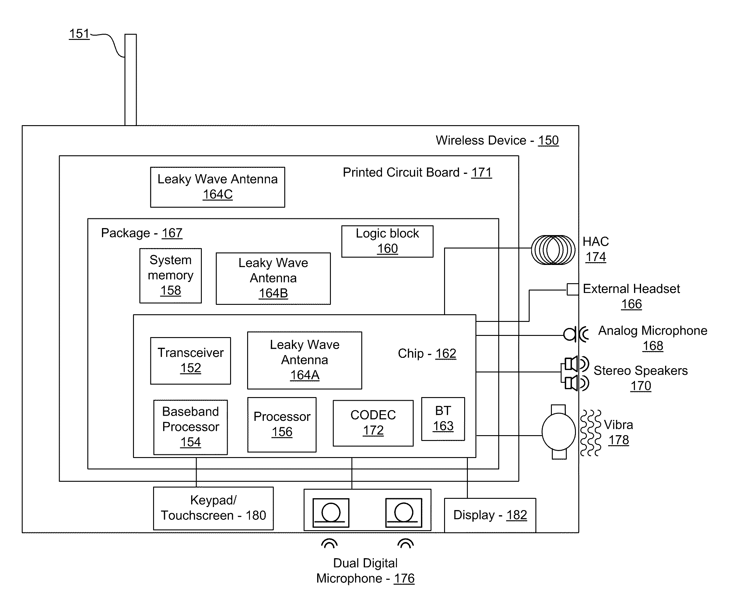
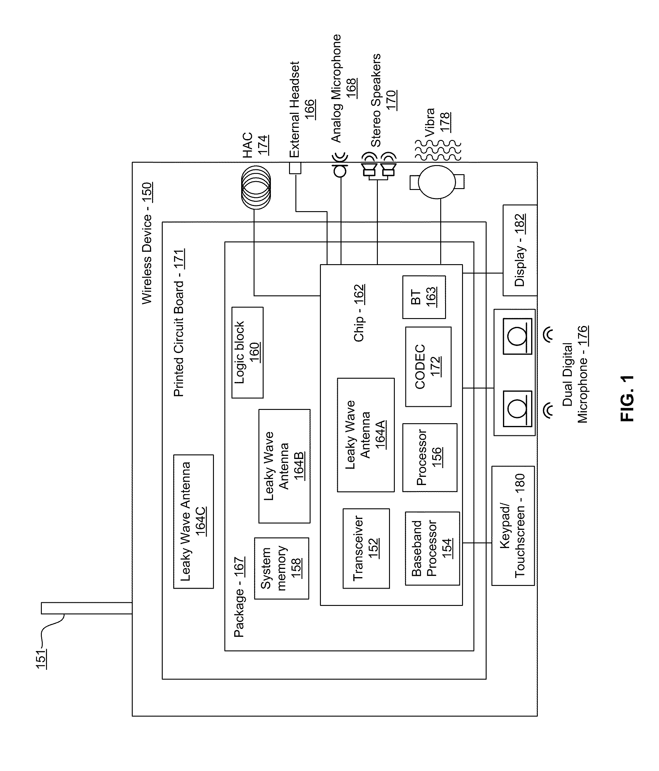
[0029]Certain aspects of the invention may be found in a method and system for a leaky wave antenna as a load on a power amplifier. Exemplary aspects of the invention may comprise configuring one or more leaky wave antennas, which are coupled to one or more power amplifiers, as a load for the one or more power amplifiers in a wireless device. RF signals may be transmitted via the one or more leaky wave antennas. The one or more leaky wave antennas may be integrated on the chip, a package to which the chip is affixed, and / or on a printed circuit board to which the chip is affixed. The leaky wave antennas may comprise an inductive load on the one or more power amplifiers or a balun for the one or more power amplifiers. The leaky wave antennas may be impedance matched to the one or more power amplifiers. One or more signals amplified by the one or more power amplifiers may be amplitude modulated by modulating a bias current in the one or more power amplifiers. An output power of the on...


PUM


Abstract

Methods and systems for utilizing a leaky wave antenna as a load on a power amplifier are disclosed and may include configuring one or more leaky wave antennas as a load for one or more power amplifiers (PAs) in a wireless device. RF signals may be transmitted via the leaky wave antennas which may be integrated on the chip, a package to which the chip is affixed, or on a printed circuit board to which the chip is affixed. The antennas may include an inductive load and/or a balun for the one or more PAs. The leaky wave antennas may be impedance matched to the PAs. The PAs may amplify a signal to be transmitted, and an output power of the PAs may be configured by controlling a bias voltage for the PAs.

Description

CROSS-REFERENCE TO RELATED APPLICATIONS / INCORPORATION BY REFERENCE[0001]This application makes reference to and claims priority to U.S. Provisional Application Ser. No. 61 / 246,618 filed on Sep. 29, 2009, and U.S. Provisional Application Ser. No. 61 / 185,245 filed on Jun. 9, 2009.[0002]This application also makes reference to:[0003]U.S. patent application Ser. No. ______ (Attorney Docket No. 21205U502) filed on even date herewith;[0004]U.S. patent application Ser. No. ______ (Attorney Docket No. 21211U502) filed on even date herewith;[0005]U.S. patent application Ser. No. ______ (Attorney Docket No. 21214U502) filed on even date herewith;[0006]U.S. patent application Ser. No. ______ (Attorney Docket No. 21227U502) filed on even date herewith;[0007]U.S. patent application Ser. No. ______ (Attorney Docket No. 21230U502) filed on even date herewith;[0008]U.S. patent application Ser. No. ______ (Attorney Docket No. 21231 U502) filed on even date herewith;[0009]U.S. patent application Ser....

Claims


Application Information

Patent Timeline
IPC IPC(8): H04B1/04
CPCH01Q1/2283H01Q13/22H01L2924/0002H01L2223/6677H01L23/66H01L2924/00
Inventor ROFOUGARAN, AHMADREZAROFOUGARAN, MARYAM
Owner AVAGO TECH INT SALES PTE LTD
Why Eureka
Try Eureka