Apparatus and method for replacing a diseased cardiac valve

a heart valve and valve body technology, applied in the field of self-expandable apparatus and methods for treating diseased cardiac valves, can solve the problems of heart pumping not only the regular volume of blood, valve repair or replacement, damage,

Inactive Publication Date: 2010-12-09
THE CLEVELAND CLINIC FOUND
View PDF25 Cites 485 Cited by
  • Summary
  • Abstract
  • Description
  • Claims
  • Application Information

AI Technical Summary

Benefits of technology

[0011]According to another aspect of the present invention, a method is provided for replacing a native cardiac valve. The native cardiac valve has at least one leaflet and is surrounded by a native cardiac valve annulus. The native cardiac valve annulus has a superior aspect and an inferior aspect. One step of the method comprises providing an apparatus including an expandable support member having a prosthetic cardiac valve secured therein and a securing member operably connected to the expandable support member. The securing member comprises an elongated body member having a first end, a second end, and a main body portion extending between the first and second ends. The second end includes a first attachment member operably connected thereto. The expandable anchoring member is placed into a delivery catheter, and the delivery catheter is then inserted into an atrial chamber. The delivery catheter is advanced until the delivery catheter is positioned within the native cardiac valve annulus. Next, the apparatus is removed from the delivery catheter so that the expandable support member obtains an expanded configuration and the first attachment member of the securing member contacts the inferior aspect of the native cardiac valve annulus and thereby secures the expandable support member in the native cardiac valve annulus.
[0013]According to another aspect of the present invention, a method is provided for replacing a native cardiac valve. The native cardiac valve has at least one leaflet and is surrounded by a native cardiac valve annulus. The native cardiac valve annulus has a superior aspect and an inferior aspect. One step of the method includes providing an apparatus comprising a securing member and a prosthetic cardiac valve operably connected to the securing member. The securing member comprises an elongated body member having a first end, a second end, and a main body portion extending between the first and second ends. The second end includes a first attachment member operably connected thereto for contacting the inferior aspect of the native cardiac valve annulus when the expandable support member is in an expanded configuration. The apparatus is placed into a delivery catheter, and the delivery catheter is then inserted into an atrial chamber. The delivery catheter is advanced until the delivery catheter is positioned within the native cardiac valve annulus. Next, the apparatus is removed from the delivery catheter so that the prosthetic cardiac valve expands in place of the native cardiac valve and the first attachment member of the securing member contacts the inferior aspect of the native cardiac valve annulus and thereby secures the prosthetic cardiac valve in the native cardiac valve annulus.

Problems solved by technology

Both of these valves are subject damage and dysfunction that requires that the valve be repaired or replaced.
As a result, the heart has to work harder by pumping not only the regular volume of blood, but also the extra volume of blood that regurgitated back into the left atrium.
The added workload creates an undue strain on the left ventricle.
This strain can eventually wear out the heart and result in morbidity.
Surgical valve replacement or repair, however, is often an exacting operation.
Surgical repair of the AV valves exposes patients (i.e., elderly patients) to many risks.

Method used


Image

  • Apparatus and method for replacing a diseased cardiac valve
  • Apparatus and method for replacing a diseased cardiac valve
  • Apparatus and method for replacing a diseased cardiac valve

Examples


Embodiment Construction

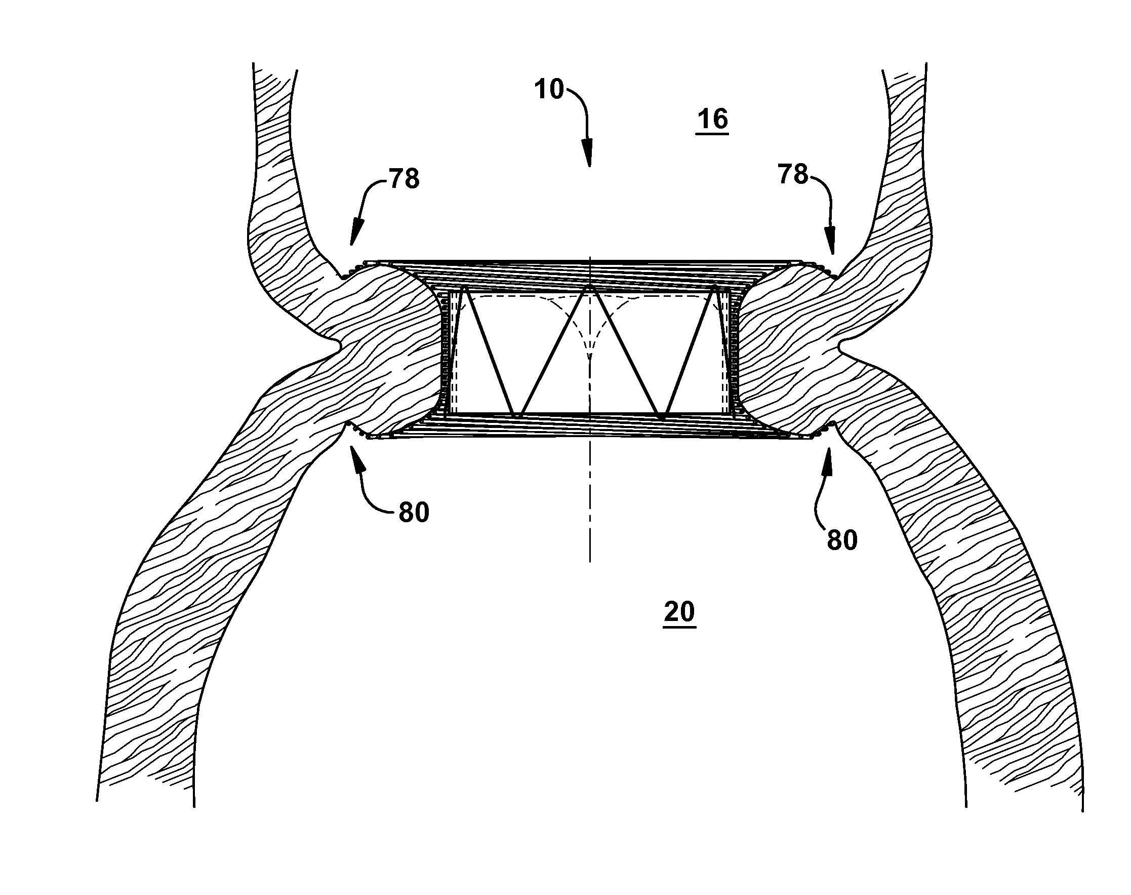
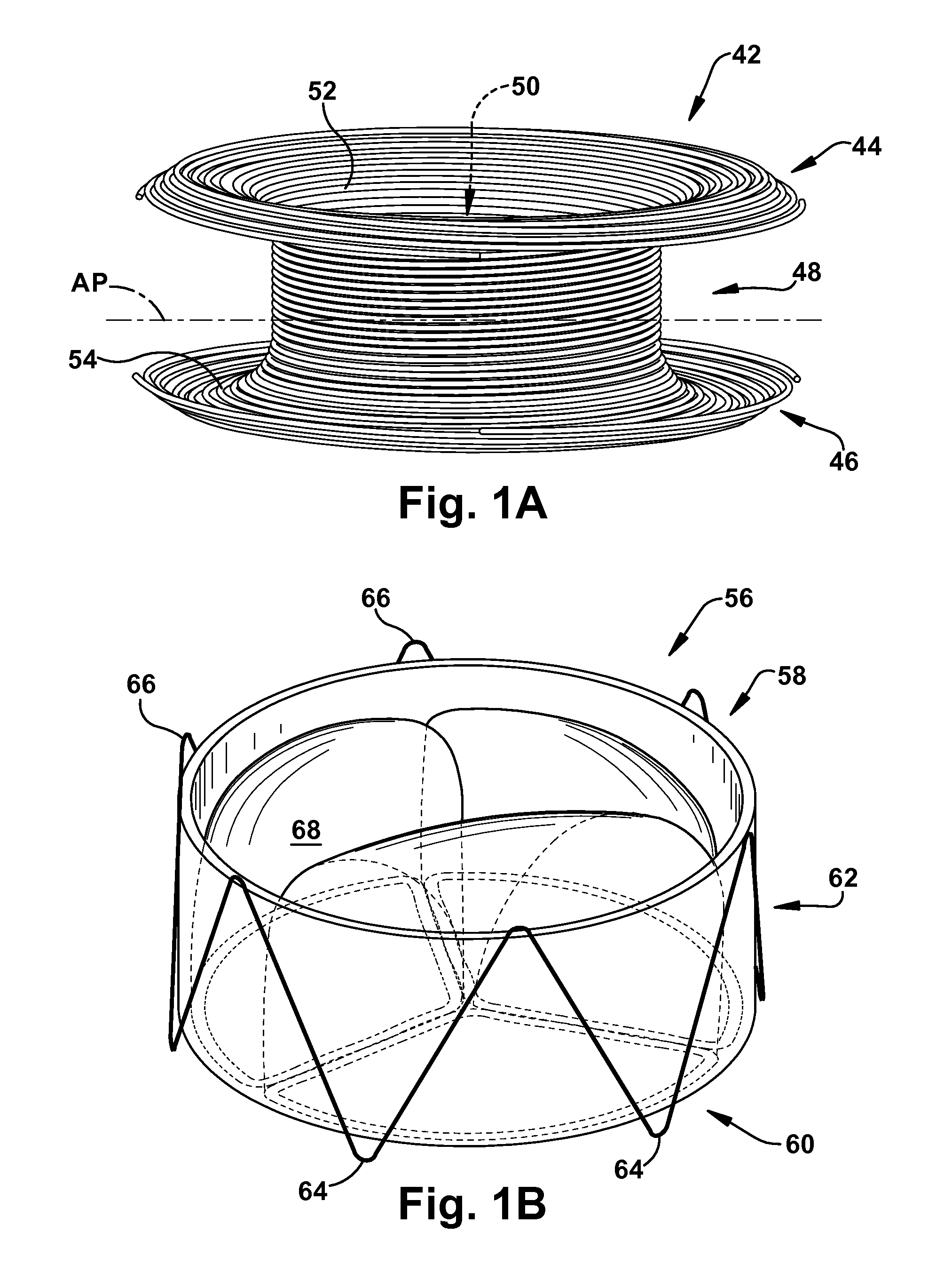
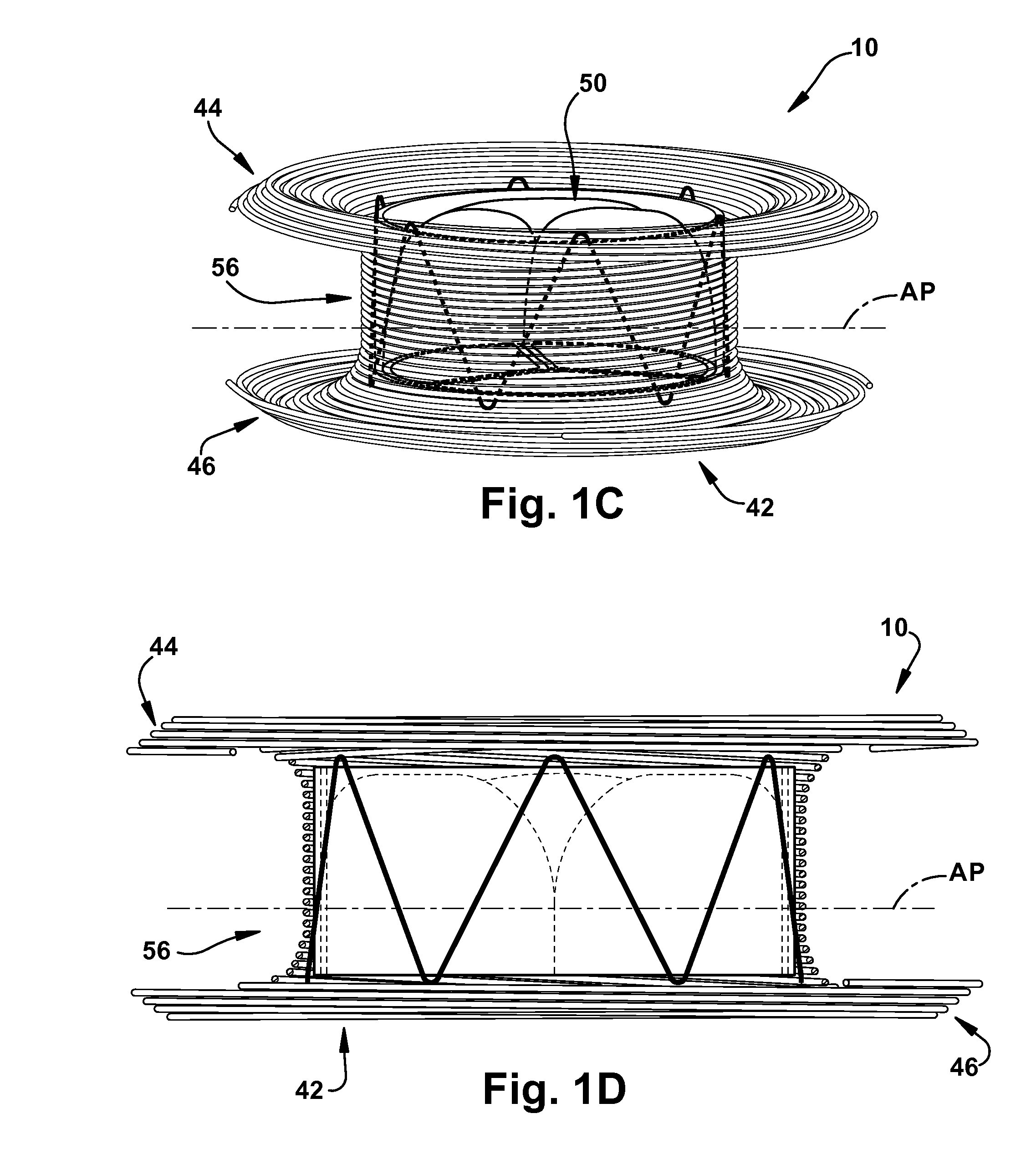
[0036]The present invention relates generally to apparatus and methods for treating heart disease, and more particularly to self-expandable apparatus and methods for treating diseased cardiac valves. As representative of the present invention, FIGS. 1A-E illustrate one embodiment of an apparatus 10 for replacing a native cardiac valve. Although the present invention is described herein as being useful for treating a diseased mitral valve, it should be appreciated that other cardiac valves, such as the tricuspid valve, the pulmonary valve, and the aortic valve are also treatable according to the present invention.

[0037]FIG. 2 shows a human heart 12. The human heart 12 contains four chambers: the right and left atria 14 and 16 and the right and left ventricles 18 and 20. The thin-walled right atrium 14 receives deoxygenated blood from the superior vena cava 22, the inferior vena cava (not shown), and from the coronary sinus (not shown). The thin-walled left atrium 16 receives oxygenat...


PUM


Abstract

An apparatus is provided for replacing a native cardiac valve. The native cardiac valve has at least one leaflet and is surrounded by a native cardiac valve annulus having superior and inferior aspects. The apparatus comprises a barbell-shaped, expandable anchoring member including first, second, and main body portions extending between the end portions. The main body portion includes a channel defined by inner and outer surfaces. Each of the first and second end portions has a diameter greater than the diameter of the main body portion. The first and second end portions are sized to respectively contact the superior and inferior aspects of the native cardiac valve annulus when the expandable anchoring member is in an expanded configuration. The apparatus also includes an expandable support member operably disposed within the main body portion of the expandable anchoring member, and a prosthetic cardiac valve secured within the expandable support member.

Description

RELATED APPLICATION[0001]This application claims priority from U.S. Provisional Application No. 61 / 173,782, filed Apr. 29, 2009, the subject matter of which is incorporated herein by reference.TECHNICAL FIELD[0002]The present invention relates generally to apparatus and methods for treating heart disease, and more particularly to self-expandable apparatus and methods for treating diseased cardiac valves.BACKGROUND OF THE INVENTION[0003]There are two atrioventricular (AV) valves in the heart; one on the left side of the heart and one on the right side of the heart. The left side AV valve is the mitral valve and the right side AV valve is the tricuspid valve. Both of these valves are subject damage and dysfunction that requires that the valve be repaired or replaced.[0004]The mitral and tricuspid valves differ significantly in anatomy. While the annulus of the mitral valve is generally D-shaped, the annulus of the tricuspid valve is more circular. The effects of valvular dysfunction v...

Claims


Application Information

Patent Timeline
Patent Type & Authority Applications(United States)
IPC IPC(8): A61F2/24
CPCA61F2/2418A61F2/2436A61F2220/0008A61F2220/005A61F2220/0066A61F2230/0054A61F2230/0078A61F2250/006A61F2/2412A61F2210/0004A61F2210/0014A61F2220/0075A61F2230/0069A61F2250/0098A61F2310/00023
Inventor NAVIA, JOSE LUISCHEN, JI-FENGZHOU, QUN
Owner THE CLEVELAND CLINIC FOUND
Why Eureka
Try Eureka