Artificial cementless hip prosthesis stem

a hip prosthesis and cementless technology, applied in the field of artificial cementless hip prosthesis stems, can solve the problems of high possibility of suffering from pulmonary embolism, high damage to bone and/or sharp pain of patients, etc., and achieve the effect of lowering the price of the stem, reducing the working load during the making process of the stem, and reducing the risk of pulmonary embolism

Active Publication Date: 2010-12-09
B I TEC
View PDF8 Cites 20 Cited by
  • Summary
  • Abstract
  • Description
  • Claims
  • Application Information

AI Technical Summary

Problems solved by technology

It is impossible to excavate a deep hollow that agrees perfectly with a ready-made stem in the femur which is different in every patient.
The former requires less time for uniting them than the latter does, but un-reacted monomer may lixiviate from the cement, and taking off the stem from the femur is very hard during the re-operation, furthermore, there is a high possibility of suffering from pulmonary embolism, so that recently the latter method has also been researched well to develop the artificial hip prosthesis stem.
Even if the integrated value of the stress acted on the interface agrees with the transmitted load, the stress concentration occurring locally on the interface causes damage of bone and / or sharp pain to patients in the case that the stress is larger than the allowable strength of the surface corresponding thereto.
If the end of interface of the deep hollow cannot withstand the load under such a distribution, it means that the stem cannot be applied to a patient in spite of the fact that the overload is not charged on him.
Besides, if the stem loosens at the proximal portion, Micro-Movement occurs to make the metallic worn powder therefrom, which may be carcinogenic.
Since it is not easy that the figure of metallic stem agrees with that of the deep hollow, Fit and Fill, which mean a fitting rate to the wall of a deep hollow and a filling rate in the cross section of a hollow, are not expected to be very high.
These phenomena force the femur to be charged by spotty loads on the contacting surface independently of the distribution of load in FIG. 15, causing the destruction of bones and interfacial separation.
Moreover, the serious problem on using the metallic stem is the metallic fatigue caused by applying it to the part of movable structure.
Since the metallic stem mentioned above is isotropic, the rigidity thereof cannot be decreased at both the proximal end and the distal end to the same degree of that of cortical bone, resulting in that the high shearing stress caused by the tension / compression and the torsion can not be checked at both the ends of the stem.
However, in the case of the composite material stem overlaid with fiber woven cloth and / or uni-directional fiber for reinforcement and the resin as the matrix, the shoulder which the metallic stem always has forces the fiber woven cloth wrinkle so that the laminating work comes to be rather difficult.
However, Fit and Fill at the epiphysis will decrease if the stem does not have a shoulder, resulting in increase in the contacting area with the spongiosa having low durability and in requirement of much time and technical skill for inserting the stem into the deep hollow being curved complicatedly.
Therefore, the cortical bone 75B is damaged when the stress concentrates on the weakened part, so that it will lose the property to withstand the load, resulting in the failure of the function as an artificial hip joint.
It is very difficult to decrease in the rigidity of epidermis 77 at the epiphysis of the composite material stem, for the epidermis is extended to the neck 66a which supports the spherical head 72 and the cavity 79 cannot be extended till the vicinity of the neck where the rigidity has to be high, consequently, the artificial hip joint of FIG. 16 can not be always applied to the patients of osteoporosis or the like, resulting in the limit of application thereof.
The process to form the stem cannot be easily divided, for it consists of single parts, or many complicated processes are required.
Not only the pressure control in the mold is difficult but also the miniaturization and lightening of the mold does not progress.
Even partially, ready-made stems are not still usable consequently, inexpensive stems are unavailable.

Method used


Image

  • Artificial cementless hip prosthesis stem
  • Artificial cementless hip prosthesis stem
  • Artificial cementless hip prosthesis stem

Examples


Embodiment Construction

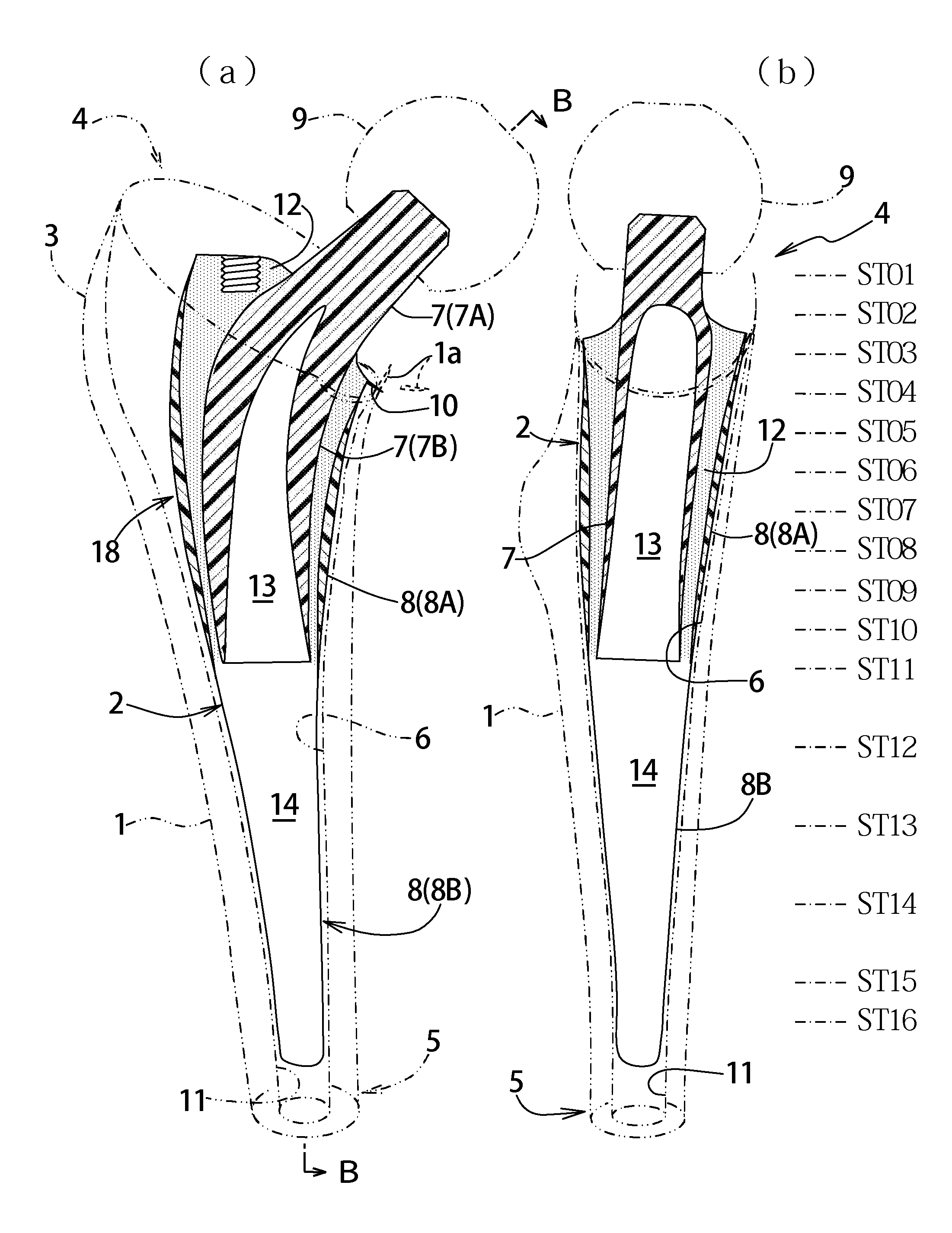
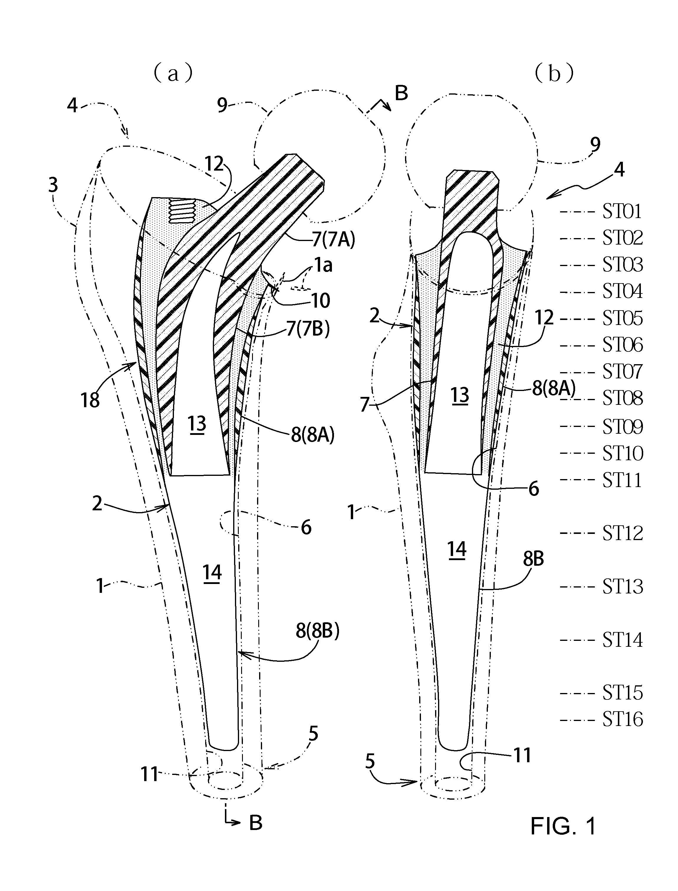
[0076]Referring to the drawings of the embodiments, an artificial cement-less hip prosthesis stem according to the present invention is disclosed as follows; FIG. 1(a) is a sectional view in which a stem 2 is implanted into a femur 1, and (b) is a sectional view taken along lines B-B in (a), wherein the stem is implanted in a deep hollow 6 extending from the epiphysis 4 to the diaphysis 5 of the femur by excising some spongiosa and a part of medulla so as not to pass through a greater trochanter 3, gradually united with the femur 1 by Bone-Growth, enabling the artificial cement-less hip prosthesis stem to eliminate the interfacial separation.

[0077]The stem 2 mainly consists of an inner construct 7 and an outer construct 8, the former is provided with a neck 7A and an inner body 7B, the latter is provided with an outer body 8A and a leg 8B. The neck 7A is engaged with a spherical head 9 which works as a joint in cooperation with a socket, not shown, fixed to a pelvis, so as to transm...


PUM

PropertyMeasurementUnit
angleaaaaaaaaaa
shearing stressaaaaaaaaaa
anglesaaaaaaaaaa

Abstract

The purpose of the invention is to eliminate not only the shearing stress concentration occurring at a distal end of a stem but also that at a proximal end thereof so that a load acted on a hip joint can be distributed collectively on the proximal portion of the stem corresponding to transmission route in a normal state and the range of variation of the stress distribution on the proximal portion comes to be as narrow as possible on the whole. An artificial cement-less hip prosthesis stem which comprises an inner construct 7 reacted with the load acted on the hip joint and an outer construct 8 transmitting the load acted on the inner construct to a femur 1. The former construct has an inner body 7B reacted with the load transmitted from a neck 7A. The latter construct has both an outer body 8A which is bell mouth-shaped toward epiphysis so as to surround the inner body 7B and a leg 8B extending toward medullary cavity. The torsional rigidity given to the proximal end and the distal end of the outer body 8A and the leg 8B is regulated lower than the torsional rigidity given to the intermediate portion 18 of the outer body 8A,

Description

TECHNICAL FIELD[0001]The present invention relates to an artificial cement-less hip prosthesis stem, more particularly, to a stem made of composite material, which can reduce an unfavorable load acted on a femur not only by eliminating the concentration of shearing stress occurring at both the proximal end and the distal end of the interface between the stem and the femur, but also by transmitting the load charged on the hip prosthesis through the proximal portion as well as in a normal state.BACKGROUND ART[0002]As shown in FIG. 13, a hip joint in which a pelvis 61 is connected with a femur 62 by a caput 63 which works as a spherical bearing, enables the movements such as uprightly standing, walking, sitting-down and the like. The femur 62 has a greater trochanter and lesser trochanter at the proximal portion thereof, and gluteus medius 65 connected with the greater trochanter 64 at the epiphysis controls movements of the femur. The break of spherical bearing due to an accident or t...

Claims


Application Information

Patent Timeline
Patent Type & Authority Applications(United States)
IPC IPC(8): A61F2/36
CPCA61F2/30767A61F2/30942A61F2/30965A61F2/36A61F2/3609A61F2/3662A61F2/367A61F2/3676A61F2/4607A61F2002/30004A61F2002/30014A61F2002/30332A61F2002/30448A61F2002/30563A61F2002/30604A61F2002/30677A61F2002/3068A61F2002/30738A61F2002/30797A61F2002/3082A61F2002/30828A61F2002/30919A61F2002/30948A61F2002/30957A61F2002/30975A61F2002/3611A61F2002/3617A61F2002/3625A61F2002/3631A61F2002/365A61F2002/3652A61F2002/3692A61F2002/4619A61F2002/4629A61F2220/0033A61F2220/005A61F2250/0014A61F2250/0018A61F2250/0068A61F2310/00023A61F2310/00029A61F2310/00796A61F2002/30593A61F2002/30652A61F2/32A61L27/00
Inventor BANDOH, SHUNICHIZAKO, MASARUSUGANO, NOBUHIKO
Owner B I TEC
Why Eureka
Try Eureka