Methods in Mixed Network and Host-Based Mobility Management

a technology of mobility management and mixed network, applied in the field of mobility management of mobile nodes in packetbased communication networks, can solve the problems of high packet delay, inefficient routing, and connection breakage of one node, and achieve the effect of preventing an increase of handover delay, reducing handover delay, and not increasing handover delay

Inactive Publication Date: 2010-12-09
PANASONIC CORP
View PDF8 Cites 96 Cited by
  • Summary
  • Abstract
  • Description
  • Claims
  • Application Information

AI Technical Summary

Benefits of technology

[0079]An embodiment according to a first aspect of the invention consists in verifying whether a mobile node is really attached to a Mobile Access Gateway that has sent a PBU message to a Local Mobility Anchor by sending an acknowledgement message not only to the IP address comprised in the just received valid PBU message, but also to the IP address comprised in the previously received valid PBU message. Such mechanism allows the detection of an attack without the need to query the policy store or AAA server at every handover time, thereby preventing an increase of the handover delay.
[0080]According to an embodiment acco

Problems solved by technology

However, since connections on higher-layers such as TCP connections are defined with the IP addresses (and ports) of the communicating nodes, the connection breaks if one of the nodes changes its IP address, e.g., due to movement.
A drawback is that if the mobile node is far away from the home network and the correspondent node is close to the mobile node, the communication path is unnecessarily long, resulting in inefficient routing and high packet delays.
The drawback is that it requires support from the visited access network.
Since the Local Mobility Anchor accepts basically any PBU message that is sent by a trusted Mobile Access Gateway, which owns a correct shared key, a problem arises if a Mobile Access Gateway gets compromised, i.e. if an attacker is able to gain control of a trusted Mobile Access Gateway.
The problem is even more severe, if the Local Mobility Anchor is also the CMIP anchor of a mobile node and the PMIP-Home Address is equal to the CMIP-Home Address.
However, a compromised Mobile Access Gateway MAG2 can send a bogus PBU for the mobile node's Home Address.
However, consulting the policy store or an AAA server for every received PBU message would significantly increase the handover delay.
However, this mechanism also significantly increases the handover delay when a mobile node enters the PMIP domain and does not solve the problem in scenario 1.
In a third aspect, the problems related to the detection of whether a binding cache entry for a mobile node at a correspondent node has been spoofed will be presented.
A drawback is that if the mobile node is far away from the home network and the correspondent node is close to the mobile node, the communication path is unnecessarily long, resulting in inefficient routing and high packet delays.
However, in contrast to IPv6 the attacker could only temporarily gain access to the path and continue the attack off-path.
A drawback of the return routability procedure and route optimization mode is that lat

Method used


Image

  • Methods in Mixed Network and Host-Based Mobility Management
  • Methods in Mixed Network and Host-Based Mobility Management
  • Methods in Mixed Network and Host-Based Mobility Management

Examples


first embodiment

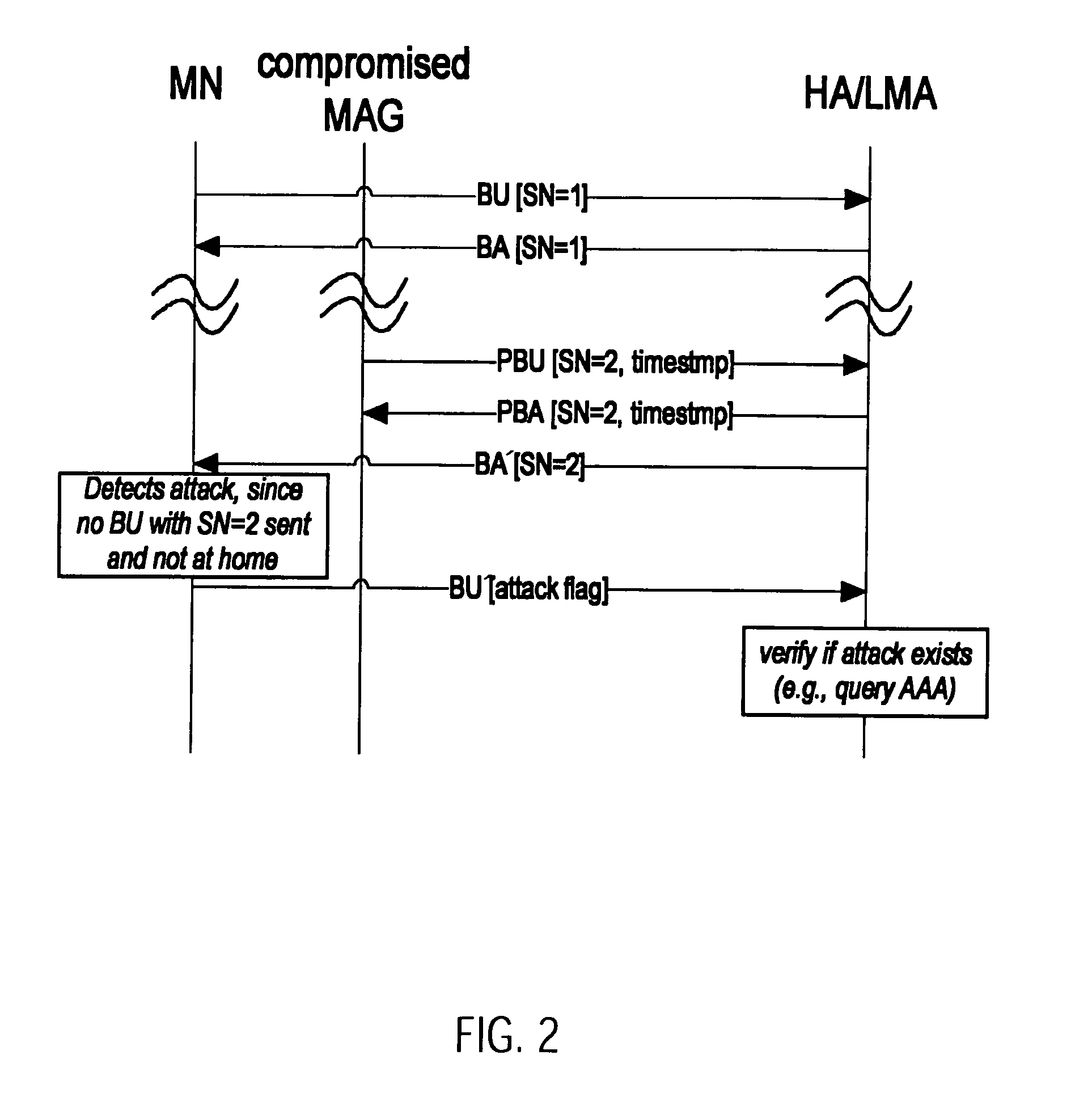
[0241]A first variant of the first embodiment according to a first aspect will be described with respect to FIG. 2. A mobile node is located in a domain implementing a client-based mobility management scheme. The mobile node thus communicates its position by sending a binding update message BU to a Local Mobility Anchor LMA. The Local Mobility Anchor LMA first checks authentication information contained in the binding update message BU to identify that this binding update BU can be trusted. After having accepted the binding update, the Local Mobility Anchor LMA then transmits a binding acknowledgment message BA to the Care-of-Address of the mobile node contained in the binding update BU to confirm that the Care-of-Address was saved in the binding cache entry of the Local Mobility Anchor LMA.

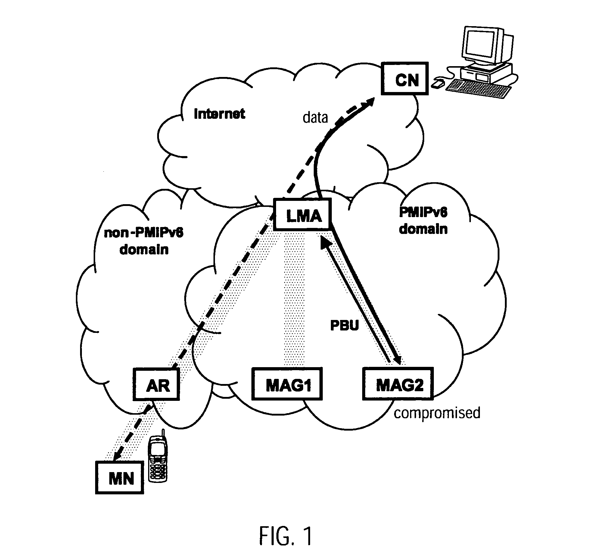
[0242]FIG. 2 illustrates an attempt by a compromised Mobile Access Gateway in a domain implementing a network-based mobility management scheme to redirect traffic destined to the mobile node. The...

second embodiment

[0261]the invention according to a first aspect will now be described with respect to FIGS. 4 and 5.

[0262]A first variant of the second embodiment according to a first aspect will be described with respect to FIG. 4. A mobile node is located in a domain implementing a client-based mobility management scheme. The mobile node thus communicates its position by sending a binding update message BU to a Local Mobility Anchor LMA. The Local Mobility Anchor LMA first checks authentication information contained in the binding update message BU to identify that this binding update BU has really been sent by the mobile node corresponding to the home address contained in the BU. After having accepted the binding update, the Local Mobility Anchor LMA then transmits a binding acknowledgment message BA to the Care-of-Address of the mobile node contained in the binding update message BU to confirm that the Care-of-Address was saved in the binding cache entry of the Local Mobility Anchor LMA.

[0263]F...


PUM


Abstract

A first aspect of the invention relates to a method for verifying an attachment of a mobile node to a network element in a network. A second aspect of the invention relates to a method to be implemented in a mobility anchor node, which detects whether a race condition between registration messages occurs and resolves the most recent location of a mobile node. A third aspect of the invention relates to a method for detecting whether a binding cache entry for a mobile at a correspondent node has been spoofed and to a method for registering a care-of address of a mobile node at a correspondent node. A fourth aspect of the invention relates to a method for providing from a mobile node to a local mobility anchor information on an attachment of a mobile node to a network element.

Description

FIELD OF THE INVENTION[0001]The invention relates, according to a first aspect, to the mobility management of a mobile node in packet-based communication networks, and more specifically, to a method for improving security at a local mobility anchor implementing both a network-based and a host-based mobility management scheme for managing the mobility of a mobile node. The invention relates to a method for detecting an attempt from a compromised network element to redirect traffic destined to a mobile node. It suggests a method for verifying an attachment of a mobile node to a network element in a network. It also provides a local mobility anchor, a mobile node and a network element that participate in this method.[0002]The invention relates, according to a second aspect, to inter-working of network-based and host-based mobility management in packet-based communication networks. It provides a method to resolve a race condition at a mobility anchor point in mixed network-based and hos...

Claims


Application Information

Patent Timeline
IPC IPC(8): H04L9/32H04L9/08
CPCH04L63/0823H04L63/1466H04W88/182H04W12/06H04W80/04H04W8/082H04W12/062H04W12/069
Inventor WENIGER, KILIANHIRANO, JUNBACHMANN, JENS LUISVELEV, GENADISCHURINGA, JON
Owner PANASONIC CORP
Why Eureka
Try Eureka