Method and device for tightness testing

a technology of tightness and test-gas, which is applied in the direction of measurement devices, instruments, structural/machine measurement, etc., can solve the problems of not being able to increase the partial pressure of test-gas and simultaneously reduce the time constant, and achieve the effects of fast system reaction time, high system sensitivity, and further increase of test-gas partial pressur

Active Publication Date: 2010-12-16
INFICON GMBH
View PDF16 Cites 12 Cited by
  • Summary
  • Abstract
  • Description
  • Claims
  • Application Information

AI Technical Summary

Benefits of technology

[0020]Optimum sensitivity is accomplished if the gas flow guided to the sensor does not exceed the carrier gas flow and if the carrier gas flow is selected to be as small as possible. Optionally, the conveyed gas can be further condensed by a compressor, with the effect that the total pressure will be above 1,000 mbar. Thereby, also the test-gas partial pressure will be further increased.
[0021]The disclosure allows for a fast system reaction time (low time constant) with simultaneous high system sensitivity.
[0022]Said higher test-gas partial pressure can be utilized for improving the detection limit of the system or for red...

Problems solved by technology

Herein, an antagonism exists: it is not possible to increase the...

Method used


Image

  • Method and device for tightness testing
  • Method and device for tightness testing
  • Method and device for tightness testing

Examples


Embodiment Construction

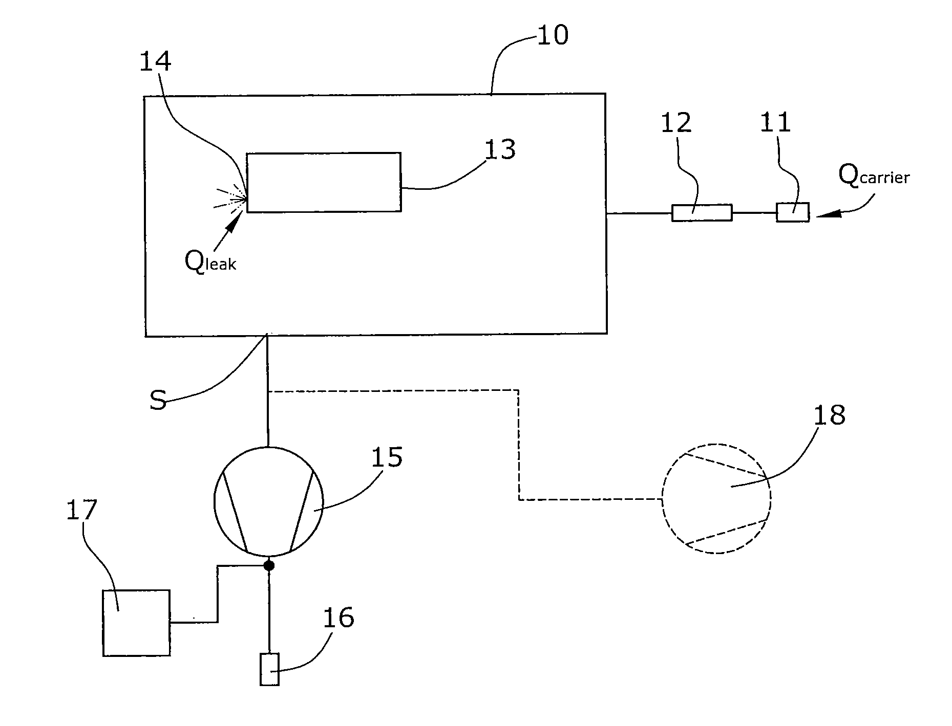
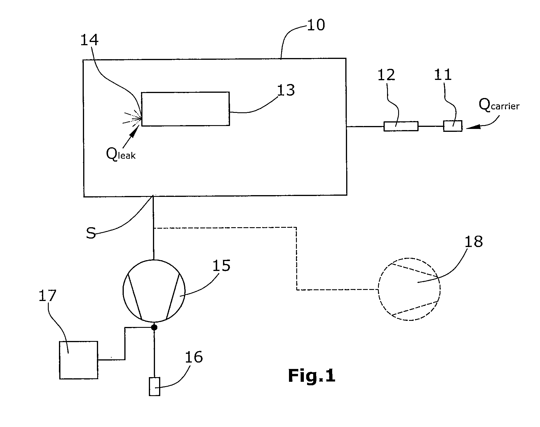
[0031]In the variant of the disclosure illustrated in FIG. 1, a test chamber 10 is provided which is closed in a vacuum-tight manner.

[0032]Into said test chamber 10, a test object 13 has been inserted. The test object is a hollow body which is to be tested for leak-tightness. For this purpose, the test object 13 has been filled with a test gas, e.g. with helium. It be assumed herein that the test object 13 has a leak 14, with test gas escaping from said leak into the evacuated test chamber 10. The escaping test gas flow is Qleak.

[0033]Connected to test chamber 10 via a suction line 19 is a suctioning condenser pump 15 for removal of the gas. Said condenser pump is a compressor whose gas outlet 16 leads into the atmosphere and will supply a total pressure Ptot=1,000 bar. Suction line 19 is connected to a carrier gas inlet 11 arranged in series with a flow sensor 12. The carrier flow at carrier gas inlet 11 is marked by Qcarrier. Within suction line 19, the test gas will mix with the ...


PUM


Abstract

A test subject, which is filled with test gas, is placed in a testing chamber, which can be evacuated. A carrier gas is conducted into the testing chamber, so that a gas mixture made of carrier gas and test gas forms therein. The gas mixture is suctioned out of the testing chamber by a compressor pump. A testing gas sensor is connected to the outlet of the compressor pump. The test gas is contained in the compressed gas mixture at a partial pressure which is increased by the compression ratio. In this manner, the sensitivity of the test gas recognition is increased and/or the time constant of the measurement is shortened.

Description

BACKGROUND[0001]1. Field of the Invention[0002]The disclosure relates to a method for tightness testing wherein a test object filled with test gas is inserted into a test chamber and wherein, by use of a test gas sensor, a gas mixture made of a test gas withdrawn from the test chamber and of a carrier gas, is examined for the presence of test gas.[0003]2. Discussion of the Background Art[0004]The disclosure further relates to a method for tightness testing wherein an evacuated test object is exposed to the external influence of a test gas, and wherein, by use of a test gas sensor, a gas mixture made of a test gas withdrawn from the test object and of a carrier gas, is examined for the presence of test gas.[0005]A known method for integral tightness testing provides that the test object filled with test gas is to be placed into a test chamber. The test chamber will be evacuated by a vacuum system, with a test gas sensor being integrated in said vacuum system. A typical test gas is he...

Claims


Application Information

Patent Timeline
IPC IPC(8): G01M3/20
CPCG01M3/226G01M3/20G01M3/229
Inventor WETZIG, DANIEL
Owner INFICON GMBH
Why Eureka
Try Eureka