Vapor process system

a technology of vapor processing and process system, which is applied in the direction of liquid hydrocarbon mixture recovery, lighting and heating apparatus, solidification, etc., can solve the problems of gas venting to the atmosphere, waste of heat energy released by burning natural gas, and waste of gas released in the intermediate pressure separator

Active Publication Date: 2016-05-31
HEATH RODNEY T +2
View PDF242 Cites 12 Cited by
  • Summary
  • Abstract
  • Description
  • Claims
  • Application Information

AI Technical Summary

Benefits of technology

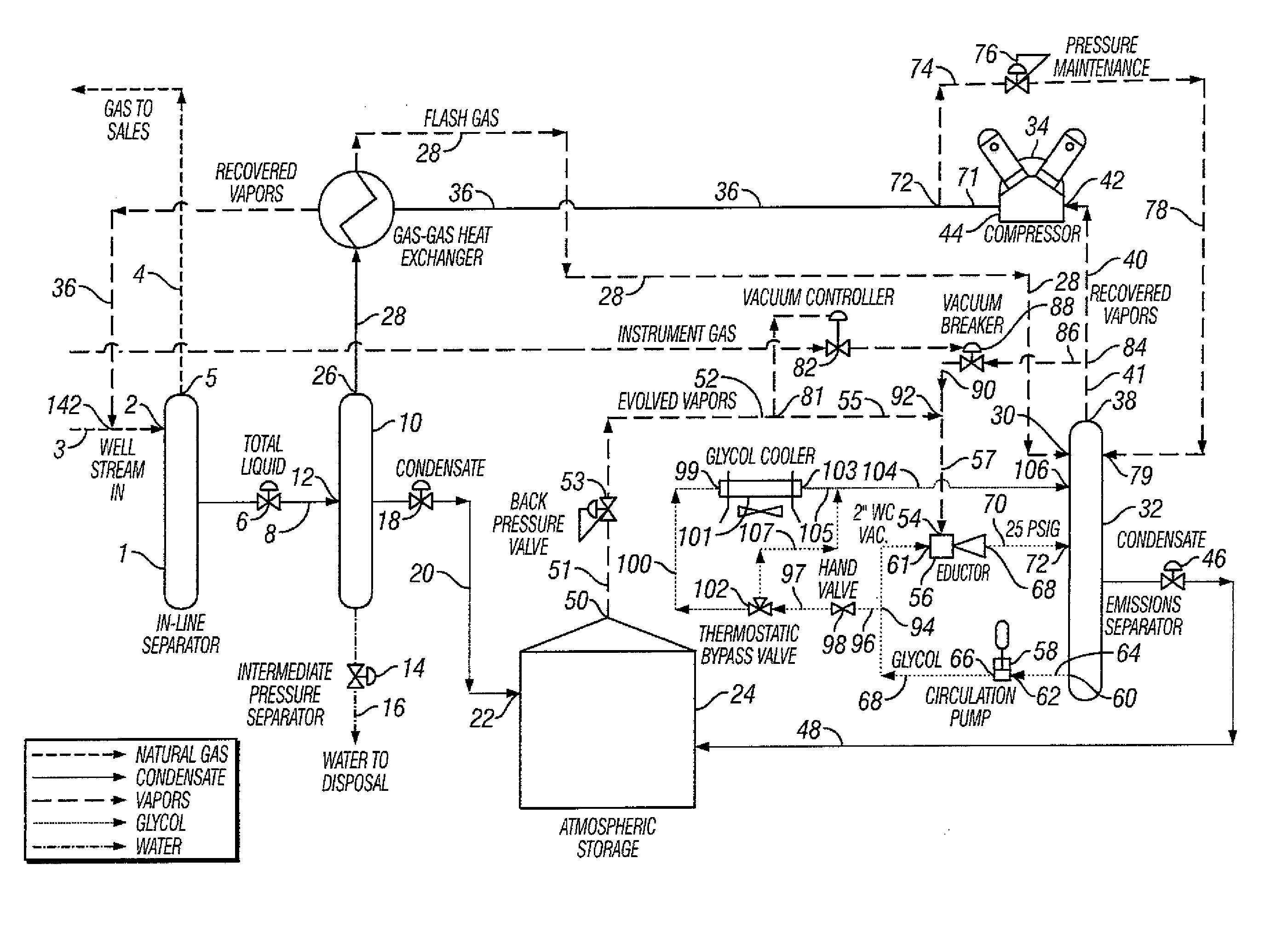
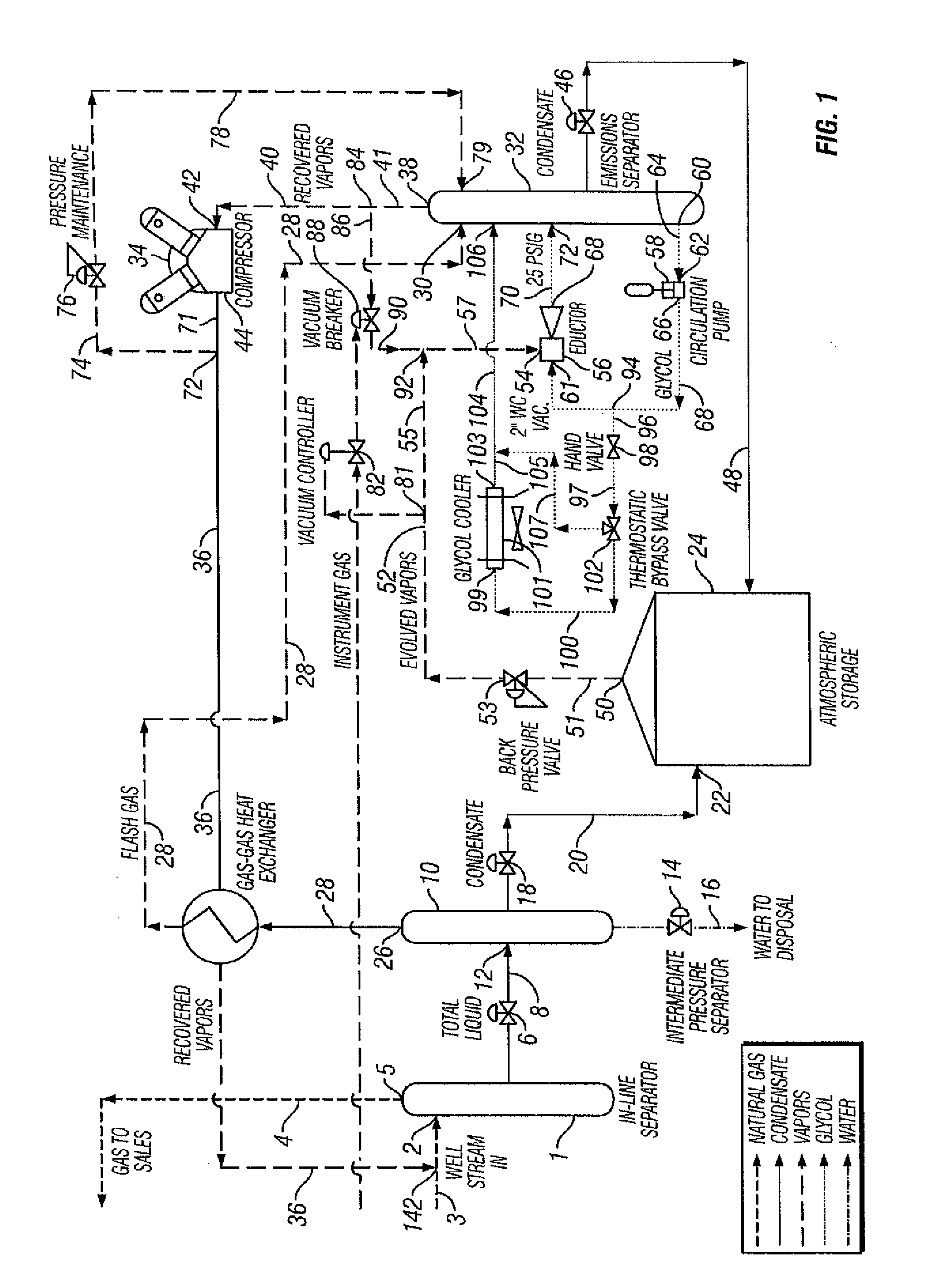
[0011]An embodiment of the present invention provides for a natural gas well vapor processing system and method comprising recovering gaseous hydrocarbons to prevent their release into the atmosphere including providing a method for preventing the gaseous hydrocarbons from returning to a liquid state.
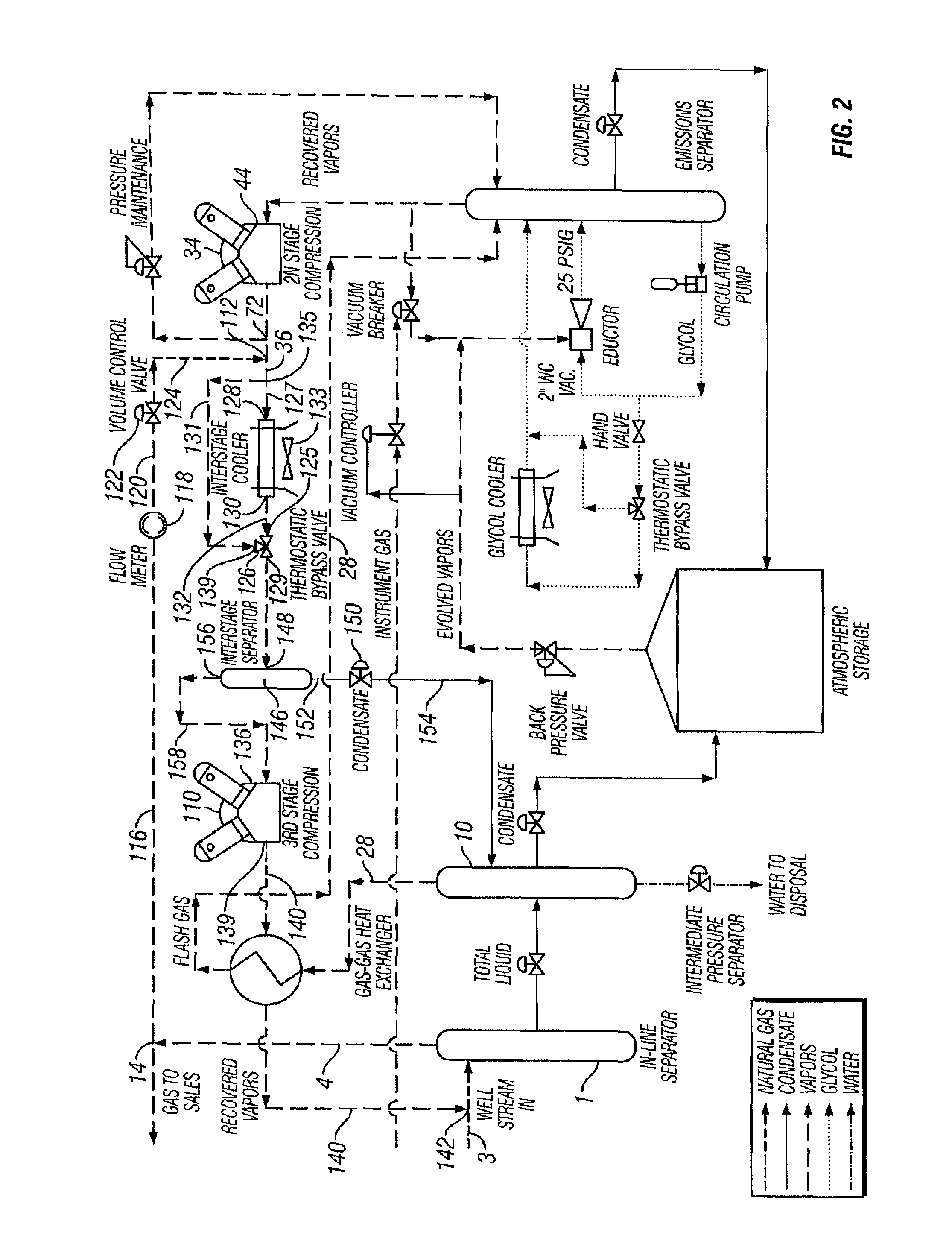
[0014]Another embodiment provides for mixing a high BTU and vapor pressure gas with a lower BTU and vapor pressure gas flowing in the pipeline to reduce the BTU and partial pressure of the compressed gas while at the same time slightly raising the BTU and partial pressure of the flowing gas stream. Lowering the BTU and partial pressure of the compressed gases reduces the tendency of the gases evolved and recovered from the tank to return to a liquid state. Any of the compressed gases that return back to a liquid state prior to passing out of the inline separator are again separated and dumped back to the storage tank.
[0015]Thus, an embodiment of the present invention provides a method for preventing the release of natural gas in a natural gas well processing system from entering the atmosphere comprising, collecting evolved gases from a storage tank, entraining the evolved gases into a fluid stream, compressing the evolved gases and fluid stream, sending the evolved gases and fluid stream to an emissions separator, and separating the gases from the fluid for further processing. Preferably, the evolved gases are collected using a vacuum, and preferably, the method further comprises providing an eductor to create the vacuum and to entrain the gasses into the liquid stream. The method preferably further comprises mixing a first compressed gas with a second compressed gas flowing in a pipeline, the second compressed gas having a BTU lower relative to the BTU of the first compressed gas to prevent gaseous hydrocarbons in the natural gas well processing system from entering a liquid state.
[0016]Another embodiment provides a method for preventing the release of gaseous hydrocarbons at a natural gas well processing system from entering the atmosphere, the method comprising providing an emissions separator, sending to the emissions separator the entrained gases that evolve form hydrocarbon liquids when the liquids are separated from a flowing gas stream at higher pressure and put in the lower pressure of an intermediate separator, sending the gaseous hydrocarbons to a compressor and compressing the gaseous hydrocarbons, and sending the compressed gaseous hydrocarbons to a flowing gas stream for further processing or point of sale.

Problems solved by technology

Without a means to recover the entrained natural gas or a means designed to collect and burn the entrained natural gas, the entrained natural gas released in the intermediate pressure separator will be vented to the atmosphere and wasted.
In most systems designed to collect and burn the entrained natural gas, the heat energy released by burning the natural gas is wasted to the atmosphere.
Again, without a system to either recover or burn the gases released from the hydrocarbon liquids dumped to the storage tank, the gases will vent to the atmosphere and be wasted.
In addition to operating problems that can occur with the currently available recovery systems, the biggest problem that has limited their application has been capital cost, and the systems have generally been applied to gas wells that have operated at pressures of 250 psig or less and that have produced volumes of hydrocarbon liquids in the range of 100 barrels per day or more.
Some of the problems with pumping gas wells have been gas locking (a condition where the pumping barrel fills with gas and no fluid can be pumped), gas interference (a condition where the pumping barrel only partially fills with fluid each stroke of the pump), and fluid pounding (a condition where the downward stroke of the pump contacts the fluid in a less than fluid filled barrel).

Method used


Image

  • Vapor process system
  • Vapor process system
  • Vapor process system

Examples


Embodiment Construction

[0022]The present invention provides a pumping system to replace plunger lifts used on natural wells. For example, in one embodiment, the pumping system such as that disclosed and marketed by Unico, Inc. (“Unico”) (or other appropriate) pumping system can be used with an engine such as that provided by Marathon Engine Systems (or other appropriate engine) to replace plunger lifts on natural gas wells. Replacing the plunger lift increases a well's production time by eliminating the lost production time associated with shutting down the well to allow the plunger to fall to the bottom as well as eliminating the lost production time required for the well to build up enough pressure to cause the plunger to rise to the surface. Often, the lost production time is greater than a well's production time. Besides increasing a well's production time, the Unico pumping system further increases a well's production by lowering the pressure the producing formation is producing against. The fluids p...


PUM

PropertyMeasurementUnit
pressuresaaaaaaaaaa
pressuresaaaaaaaaaa
pressuresaaaaaaaaaa

Abstract

The present invention provides for a natural gas well vapor processing system and method comprising recovering gaseous hydrocarbons to prevent their release into the atmosphere including providing a method for preventing the gaseous hydrocarbons from returning to a liquid state.

Description

CROSS-REFERENCE TO RELATED APPLICATIONS[0001]This application claims the benefit of the filing of U.S. Provisional Patent Application Ser. No. 60 / 612,278, entitled “Vapor Process System”, filed on Sep. 22, 2004, and the specification of that application is incorporated herein by reference.BACKGROUND OF THE INVENTION[0002]1. Field of the Invention (Technical Field)[0003]The present invention relates to vapor processing systems for use with natural gas wells. The invention comprises a pumping system used with an engine instead of plunger lifts and can be used to remove evolved gases from hydrocarbon liquids to storage at or near atmospheric pressure.[0004]2. Background Art[0005]In addition to producing natural gas, many natural gas wells produce hydrocarbon liquids and water. The liquids, hydrocarbons and water, are separated from the flowing natural gas by a separator installed in the line carrying the flowing gas stream. The inline separator may operate at pressures as high as 1,500...

Claims


Application Information

Patent Timeline
Patent Type & Authority Patents(United States)
IPC IPC(8): C10L3/12C10G5/06C10L3/10
CPCC10G5/06C10L3/10C10L3/106C10L3/12
Inventor HEATH, RODNEY T.HEATH, FORREST D.HEATH, GARY
Owner HEATH RODNEY T
Why Eureka
Try Eureka