Micromachined tuning fork gyroscopes with ultra-high sensitivity and shock rejection

Active Publication Date: 2010-12-16
RGT UNIV OF CALIFORNIA
View PDF11 Cites 116 Cited by
  • Summary
  • Abstract
  • Description
  • Claims
  • Application Information

AI Technical Summary

Benefits of technology

[0042]The illustrated embodiments of the invention further include a method of operating a vibratory rate z-axis gyroscope characterized by drive-mode and sense-mode quality factors and rate sensitivity including the steps of driving at least two decoupled vibratory tines in anti-phase motion at a predetermined drive frequency, structurally forcing the at least two decoupled vibratory tines in anti-phase motion by a levered drive-mode mechanism coupled etween the tines to eliminate spurious frequency modes of the anti-phase drive-mode motion of the tines lower than the predetermined drive frequency and to provide synchronization of drive- and sense-mode motion of the tines, and sensing dynami

Problems solved by technology

Conventional tuning fork designs with linear anti-phase drive-modes present several major drawbacks: presence of the parasitic low-frequency structural mode of in-phase vibration, limitation of the maximal achievable sense-mode quality factor by approximately half of the drive-mode quality factor due to substrate energy dissipation caused by the torque imbalance, and difficulty of maintaining mode matched condition over the practical temperature ranges.

Method used


Image

  • Micromachined tuning fork gyroscopes with ultra-high sensitivity and shock rejection
  • Micromachined tuning fork gyroscopes with ultra-high sensitivity and shock rejection
  • Micromachined tuning fork gyroscopes with ultra-high sensitivity and shock rejection

Examples


first embodiment

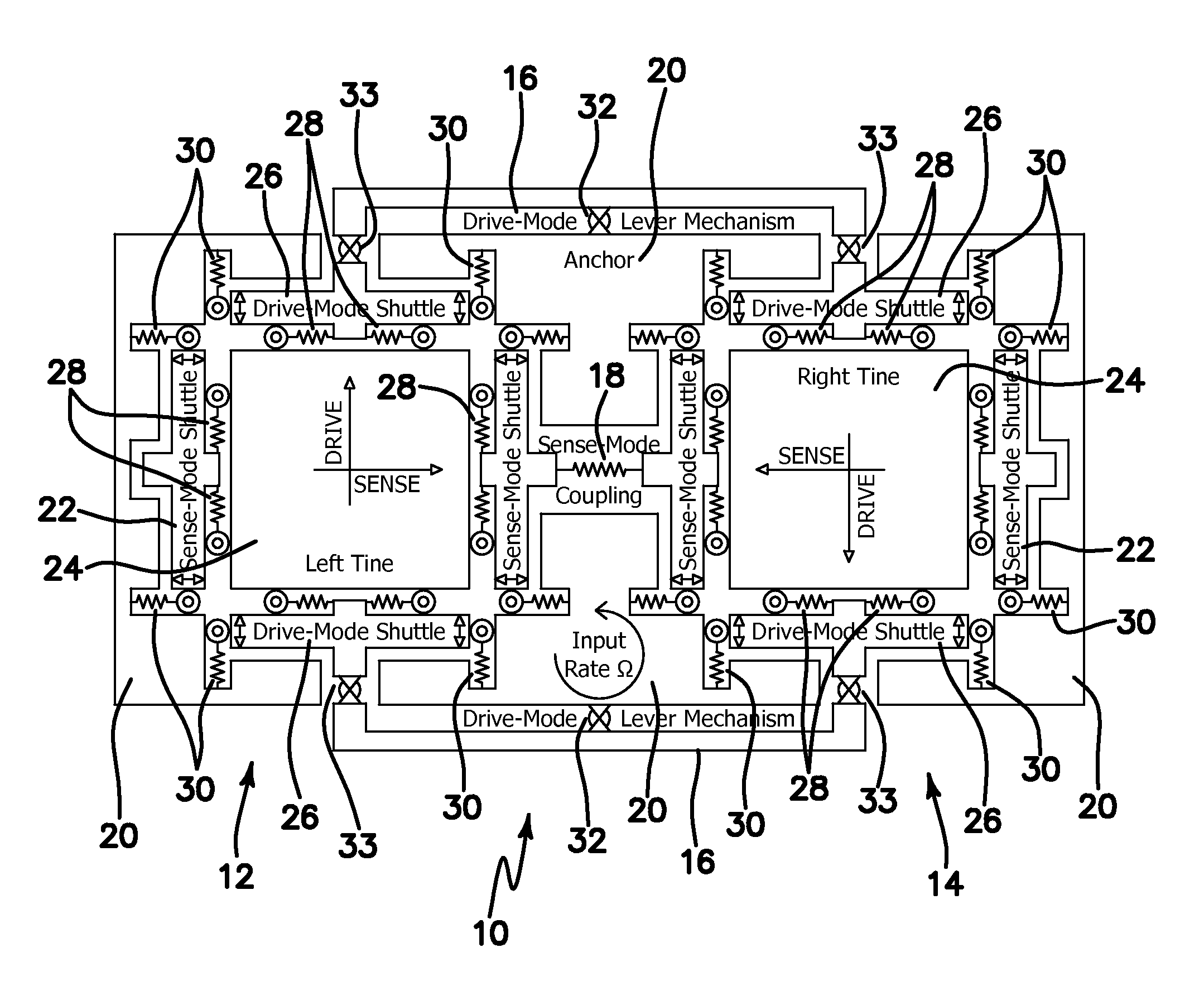
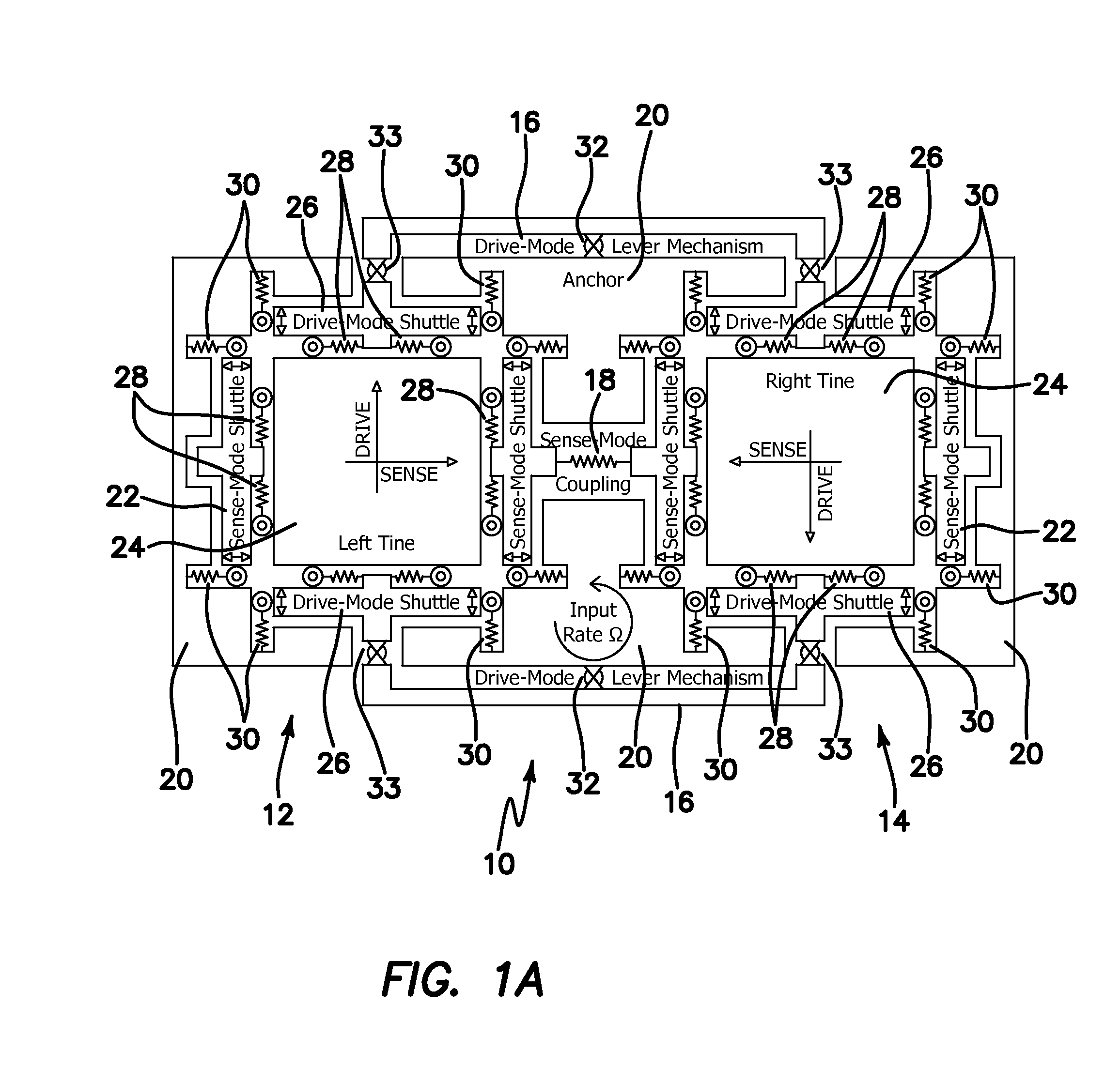
[0067]the dual mass gyroscope architecture has a structurally forced anti-phase drive-mode and a linearly coupled, dynamically balanced anti-phase sense-mode. The design utilizes two symmetrically-decoupled tines with drive- and sense-mode synchronization mechanisms, and prioritizes the sense-mode quality factor. The levered drive-mode mechanism structurally forces the anti-phase drive-mode motion and eliminates the lower frequency spurious modes. The linearly coupled, dynamically balanced anti-phase sense-mode design minimizes substrate energy dissipation leading to enhancement of the quality factor and rate sensitivity.

second embodiment

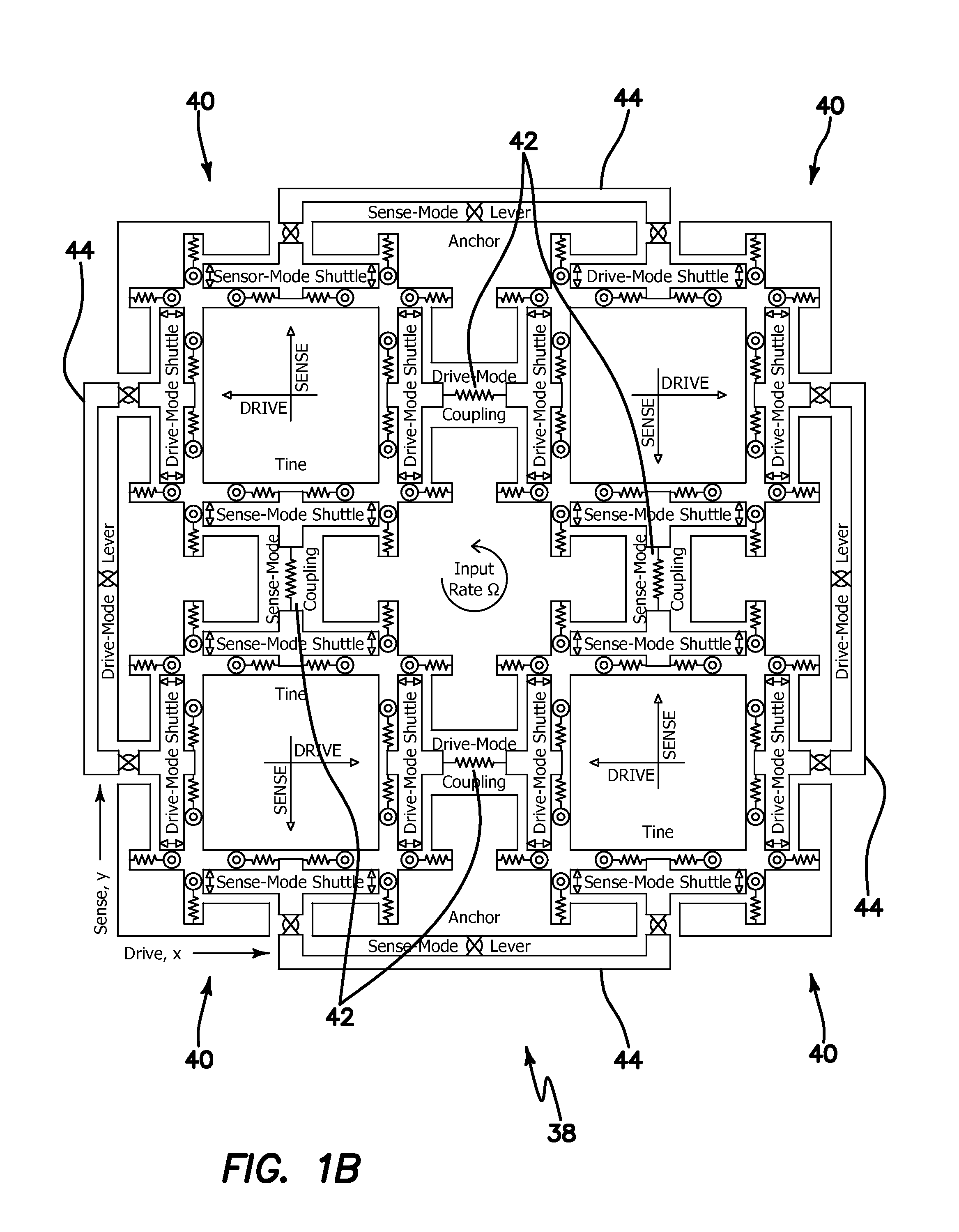
[0068]A second embodiment includes a quadruple mass gyroscope architecture which builds upon the dual mass design by coupling together two dual mass devices to achieve completely symmetric, mode-matched mechanical structure with ultra-high quality factor in both the drive- and sense-mode. The quadruple mass design of the rate sensor element preserves the ultra-high sensitivity of the dual mass design. At the same time, the quadruple mass design provides complete mechanical rejection of external vibrations and shocks along both drive and sense axes and improved robustness to fabrication imperfections and temperature induced frequency drifts.

[0069]Prototypes of the gyroscopes were designed, implemented, and fabricated using an in-house, wafer scale silicon-on-insulator (SOI) bulk micromachining process, and experimentally characterized. Dual mass tuning fork gyroscope prototype characterized in vacuum demonstrated drive-mode quality factor of 67,000 and sense- mode quality factor of 1...


PUM


Abstract

A vibratory rate z-axis gyroscope is characterized by drive-mode and sense-mode quality factors and rate sensitivity and is fabricated with at least two decoupled vibratory tines, a levered drive-mode mechanism coupled between the tines to structurally force anti-phase drive-mode motion of the tines at a predetermined drive frequency, to eliminate spurious frequency modes of the anti-phase drive-mode motion of the tines lower than the predetermined drive frequency and to provide synchronization of drive- and sense-mode motion of the tines, and a sense-mode mechanism coupled between the tines arranged and configured to provide a linearly coupled, dynamically balanced anti-phase sense-mode motion of the tines to minimize substrate energy dissipation and to enhance the sense-mode quality factor and rate sensitivity.

Description

RELATED APPLICATIONS[0001]The present application is related to U.S. Provisional Patent Application, Ser. No. 61 / 186,731, filed on Jun. 12, 2009, which is incorporated herein by reference and to which priority is claimed pursuant to 35 USC 119.GOVERNMENT RIGHTS [0002]This invention was made with Government support under Grant No. CMS0409923, awarded by the National Science Foundation. The Government has certain rights in this invention.BACKGROUND OF THE INVENTION [0003]1. Field of the Invention[0004]The invention relates to the field of vibratory z-axis gyroscopes with at least two coupled masses operating in anti-phase motion.[0005]2. Description of the Prior Art[0006]Conventional tuning fork designs with linear anti-phase drive-modes present several major drawbacks: presence of the parasitic low-frequency structural mode of in-phase vibration, limitation of the maximal achievable sense-mode quality factor by approximately half of the drive-mode quality factor due to substrate ener...

Claims


Application Information

Patent Timeline
IPC IPC(8): G01C19/56
CPCG01C19/5719G01C19/5747
Inventor TRUSOV, ALEXANDER A.SCHOFIELD, ADAM R.SHKEL, ANDREI M.
Owner RGT UNIV OF CALIFORNIA
Why Eureka
Try Eureka