Heat exchanger
a heat exchanger and heat exchanger technology, applied in indirect heat exchangers, lighting and heating apparatuses, laminated elements, etc., can solve the problems of weak metallic bonding, difficult pressurization of copper powder on the outer circumference face of the tube with a strong force, etc., and achieve the effect of raising the heat transmission performance of the heat exchanger
- Summary
- Abstract
- Description
- Claims
- Application Information
AI Technical Summary
Benefits of technology
Problems solved by technology
Method used
Image

Examples
first embodiment
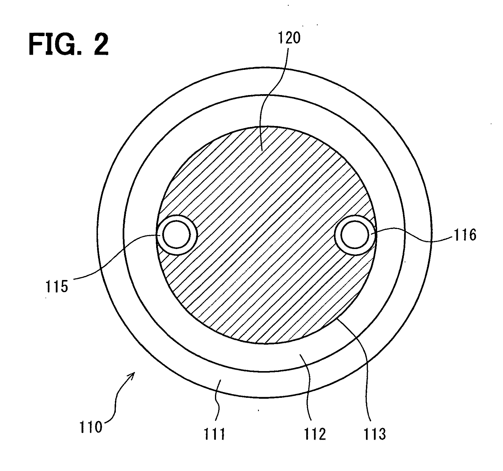
[0028]A heat exchanger 100 of a first embodiment will be described with reference to FIGS. 1 and 2.
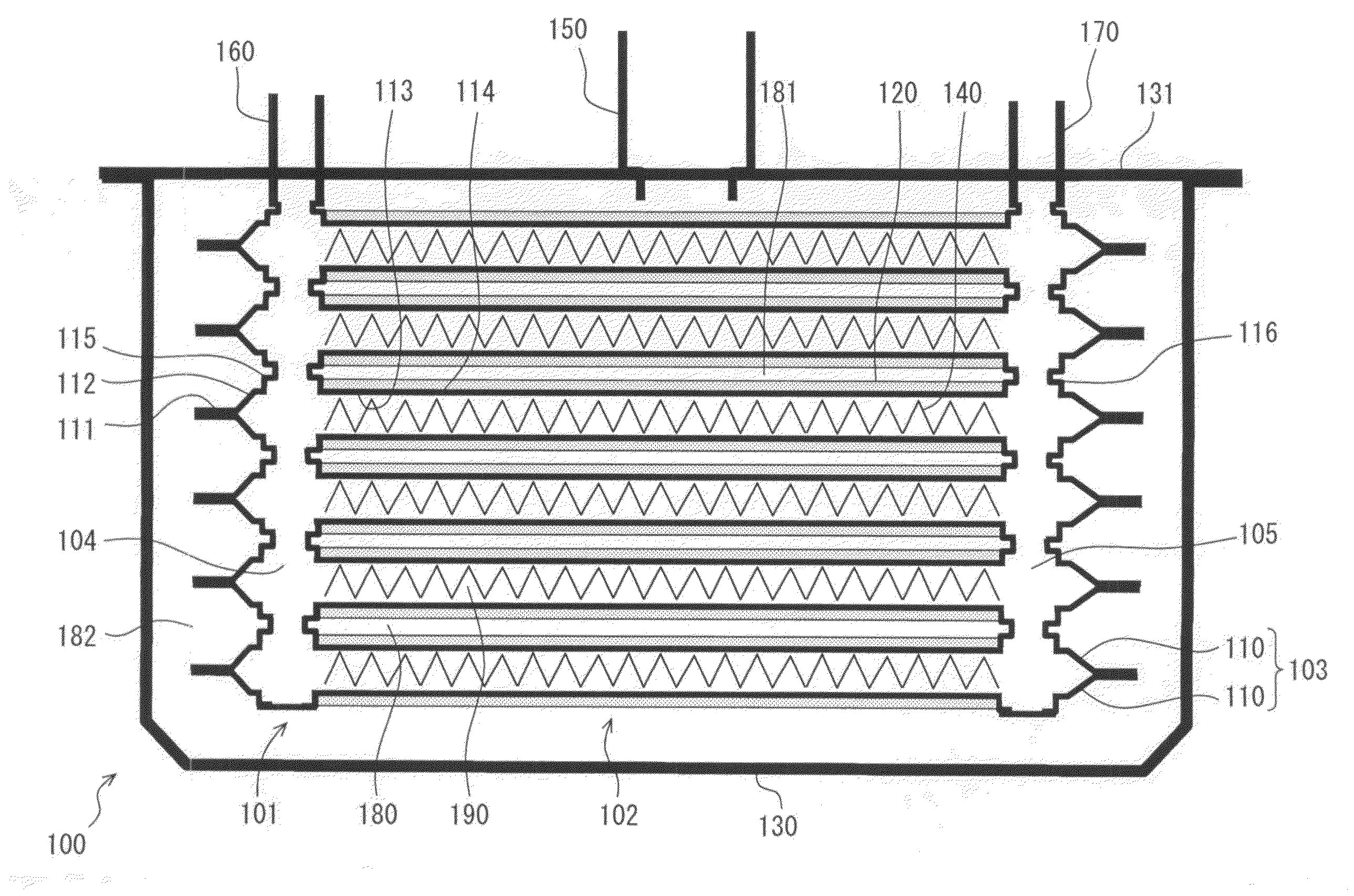
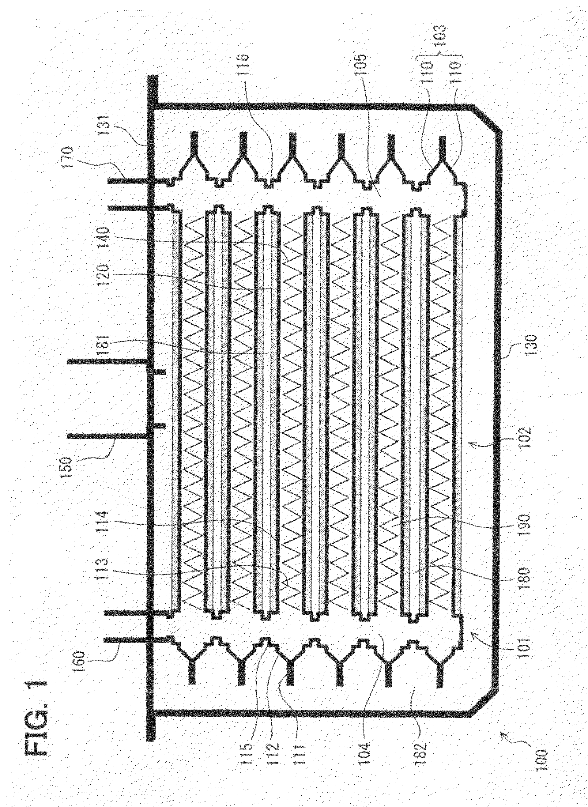
[0029]The heat exchanger 100 is used for exchanging heat between adsorbent contained in a sintered member 120 and heat exchange medium passing through a second passage 190. When water is evaporated into water vapor to be adsorbed by the adsorbent, the heat exchange medium is cooled by latent heat generated by the evaporation. In contrast, when the adsorbent is heated by a high temperature heat exchange medium, the adsorbed water vapor is desorbed from the adsorbent. The water vapor represents first fluid, and may correspond to gas phase medium to be adsorbed. The evaporated water may correspond to liquid phase medium to be adsorbed. The heat exchange medium represents second fluid.
[0030]As shown in FIG. 1, the heat exchanger 100 has a heat exchange portion 101, a casing 130, a lid 131, a communication tube 150, an inlet tube 160 and an outlet tube 170. In the heat exchange portion 101,...
second embodiment
[0059]A heat exchanger 200 of a second embodiment will be described with reference to FIGS. 3 and 4.
[0060]In each subsequent embodiment, the same reference number is given to the same component as the first embodiment, and its explanation is omitted. Points and features different from the first embodiment will be described.
[0061]Heat is exchanged between first fluid and second fluid in the heat exchanger 200. The heat exchanger 200 has a heat exchange portion 201, a communication tube 250, an inlet tube 260 and an outlet tube 270. Heat is exchanged between first fluid and second fluid in the heat exchange portion 201. The tubes 250, 260, 270 are connected to the heat exchange portion 201. First fluid may correspond to water, and the second fluid may correspond to coolant to cool an internal combustion engine (not shown).
[0062]The heat exchange portion 201 is constructed by layering plural adsorption modules 203. The module 203 has a first container 210a and a second container 210b. ...
third embodiment
[0104]A heat exchanger 300 of a third embodiment will be described with reference to FIGS. 6-10.
[0105]The heat exchanger 300 has cross-sections of FIGS. 7 and 8, when the heat exchanger 300 of FIG. 6 is assembled.
[0106]The heat exchanger 300 has a heat exchange portion 301. In the heat exchange portion 301, heat is exchanged between first fluid and second fluid. The first fluid may correspond to water, and the second fluid may correspond to coolant to cool an internal combustion engine (not shown).
[0107]The heat exchange portion 301 is defined by layering plural board members 310a, 310b. As shown in FIGS. 9 and 10, the board member 310a, 310b has a rectangular shape, and is made of metal such as copper. A connecting portion 311a, 311b is formed around all outer periphery of the board member 310a, 310b. As shown in FIG. 7, the connecting portion 311a, 311b extends toward a first end of the layering direction, and has a rectangular tube shape.
[0108]As shown in FIG. 8 indicating inside...
PUM
 Abstract
Description
Claims
Application Information
 - R&D
- Intellectual Property
- Life Sciences
- Materials
- Tech Scout
- Unparalleled Data Quality
- Higher Quality Content
- 60% Fewer Hallucinations
Browse by: Latest US Patents, China's latest patents, Technical Efficacy Thesaurus, Application Domain, Technology Topic, Popular Technical Reports.
© 2025 PatSnap. All rights reserved.Legal|Privacy policy|Modern Slavery Act Transparency Statement|Sitemap|About US| Contact US: help@patsnap.com