Heat exchanger having micro-channels

a heat exchanger and microchannel technology, applied in the direction of lighting and heating apparatus, stationary conduit assemblies, laminated elements, etc., can solve the problems of large amount of heat transfer, difficult to meet a spatial condition within the device for mounting the heat exchanger, and difficult to adapt the same, etc., to achieve high performance

Inactive Publication Date: 2010-12-16
AGENCY FOR DEFENSE DEV
View PDF43 Cites 38 Cited by
  • Summary
  • Abstract
  • Description
  • Claims
  • Application Information

AI Technical Summary

Benefits of technology

[0009]Therefore, in order to obviate such problems of the related art, an object of the present invention is to provide a heat exchanger capable of implementing high performance by designing micro-channels having the same flow length when an outer appearance thereof has a curvature.

Problems solved by technology

Gas-to-gas heat exchange needs a greater heat transfer area for the same heat exchange due to a low overall heat transfer coefficient, which causes difficulty in adapting the same to cases having constraint conditions of weight and space.
However, by a design of the form of a micro-channel heat exchanger, the large amount of heat transfer can be generated with maintaining a small amount of pressure drop.
However, in case of a rectangular heat exchanger designed by the related art, since the shape and outline of flow channels are simple, it is relatively easy to design the shape of the flow channels, but usually difficult to meet a spatial condition within a device for mounting the heat exchanger therein.
In particular, if an overall outline has a curvature, the design of flow channels having the same flow length becomes more difficult.

Method used


Image

  • Heat exchanger having micro-channels
  • Heat exchanger having micro-channels
  • Heat exchanger having micro-channels

Examples


Embodiment Construction

[0027]Description will now be given in detail of the present invention, with reference to the accompanying drawings.

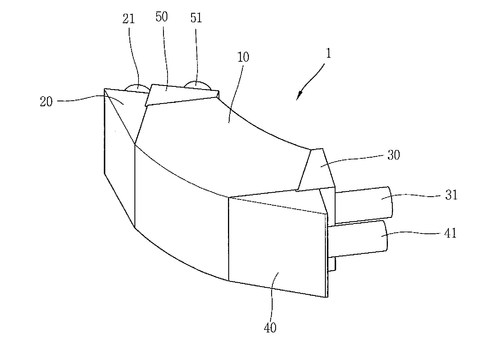
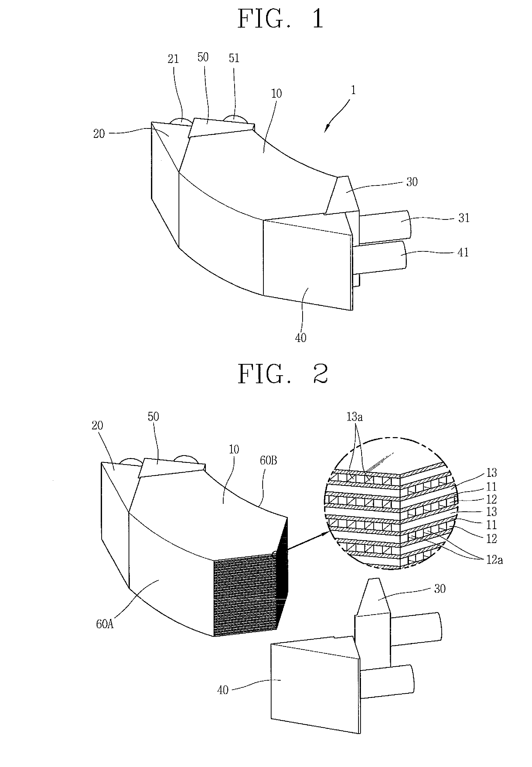
[0028]FIG. 1 is a perspective view showing one example of a micro-channel heat exchanger in accordance with the present invention. As shown in FIG. 1, a heat exchanger may include a heat exchanger body 10 having a curved shape, a high temperature fluid inlet body 20 and a low temperature fluid outlet body 50 detachably connected to one end portion of the heat exchanger body 10, and a low temperature fluid inlet body 40 and a high temperature fluid outlet body 30 attached onto another end portion of the heat exchanger body 10.

[0029]One side surface 60A of both side surfaces 60A and 60B (see FIG. 2), which define a width of the heat exchanger body 10 may have a first curvature profile, and another side surface 60B may have a second curvature profile in parallel to the first curvature profile. The first curvature profile and the second curvature profile may possibly be ar...


PUM


Abstract

Disclosed is a heat exchanger configured by laminating layers having micro-channels by adapting a micromachining, wherein the micro-channels having uniform length and cross section are constructed within a heat exchanger body in a curved outer shape, thereby minimizing deviation for each channel and improving heat transfer efficiency.

Description

CROSS-REFERENCE TO A RELATED APPLICATION[0001]This application claims the benefit of and right of priority to Korean Application No. 10-2009-0051898, filed on Jun. 11, 2009, the contents of which is incorporated by reference herein in its entirety.FIELD OF THE INVENTION[0002]The present invention relates to a heat exchanger having micro-channels formed by micromachining.BACKGROUND OF THE INVENTION[0003]Heat exchangers employed for special use are used in high temperature and high pressure environments, unlike typical heat exchangers, or required to be compact and durable in order to meet constraint conditions, such as weight, space and the like.[0004]Gas-to-gas heat exchange needs a greater heat transfer area for the same heat exchange due to a low overall heat transfer coefficient, which causes difficulty in adapting the same to cases having constraint conditions of weight and space.[0005]A printed circuit heat exchanger (PCHE), as a type of micro-channel heat exchanger, is made by...

Claims


Application Information

Patent Timeline
Patent Type & Authority Applications(United States)
IPC IPC(8): F28F3/00
CPCF28D9/0062F28F3/048F28F13/06F28F2260/02F28D1/03F28F3/02
Inventor YOO, YOUNG JUNELIM, JIN SHIKMIN, SEONG KIPARK, GEUN HONGJIN, SANG WOOKOH, KWANG YOON
Owner AGENCY FOR DEFENSE DEV
Why Eureka
Try Eureka