Spiral mixer for floc conditioning

a technology of floc conditioning and spiral mixer, which is applied in the direction of filtration separation, multi-stage water/sewage treatment, separation process, etc., can solve the problems of requiring a substantial physical footprint and initial infrastructure cost, orthokinetic aggregation (shear driven) is much faster, and the effect of reducing the size of the mixer

Inactive Publication Date: 2010-12-16
PALO ALTO RES CENT INC
View PDF35 Cites 30 Cited by
  • Summary
  • Abstract
  • Description
  • Claims
  • Application Information

AI Technical Summary

Problems solved by technology

The hydraulic retention time through the first 3 stages may be 5-10 hours, depending on the input water quality and the facility, and require a substantial physical footprint and initial infrastructu

Method used


Image

  • Spiral mixer for floc conditioning
  • Spiral mixer for floc conditioning
  • Spiral mixer for floc conditioning

Examples


Embodiment Construction

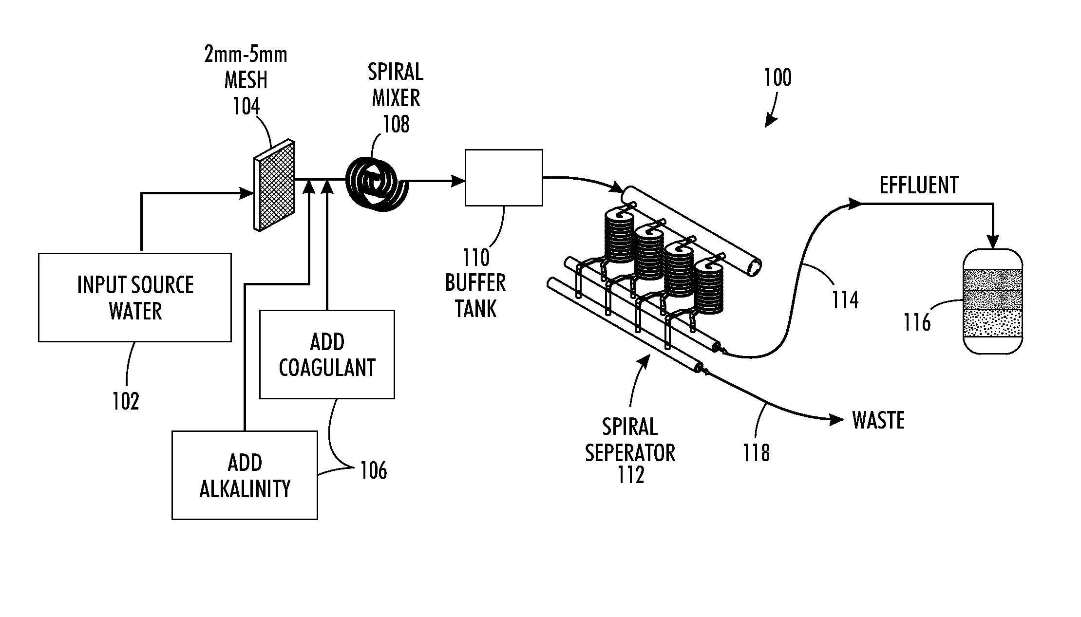
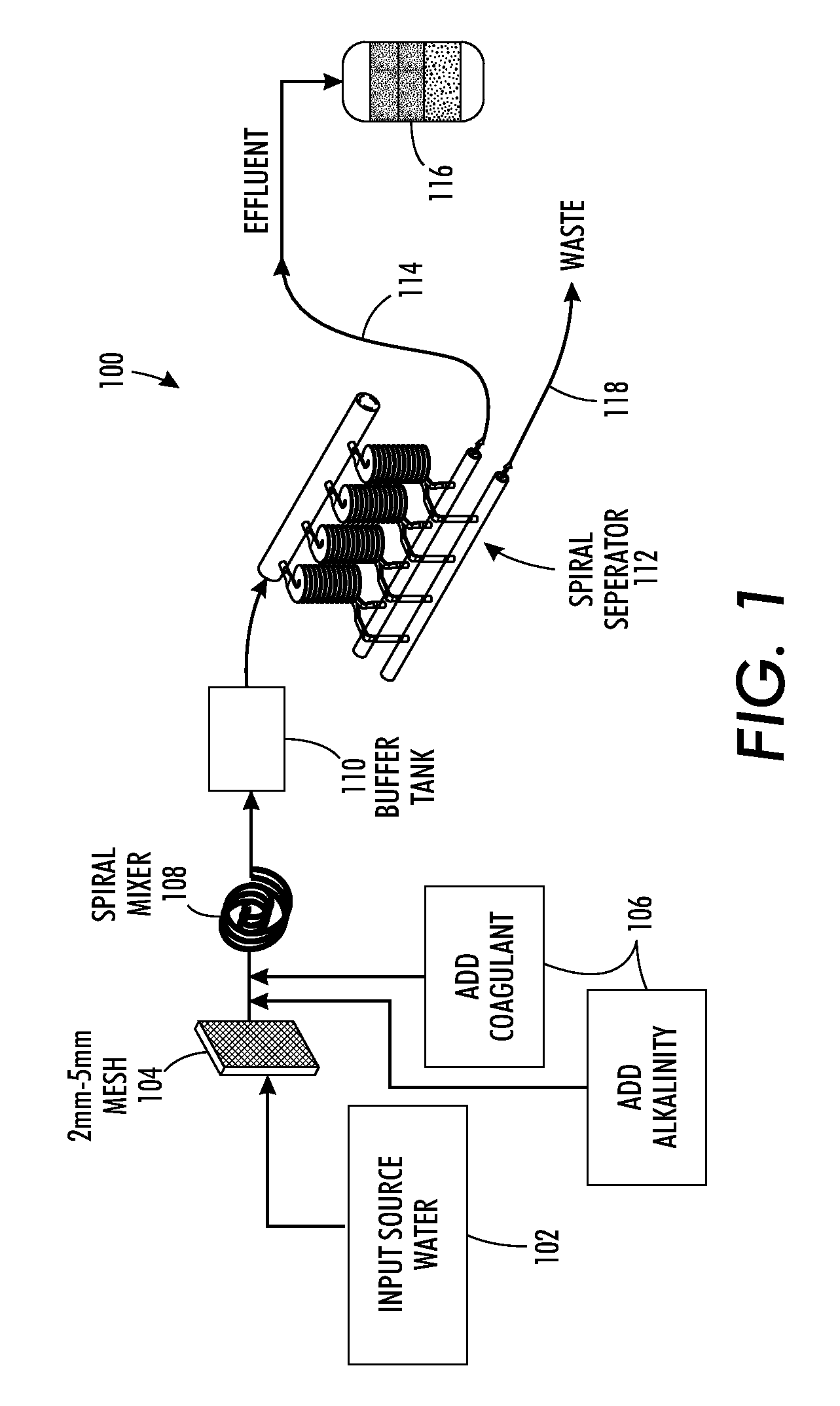
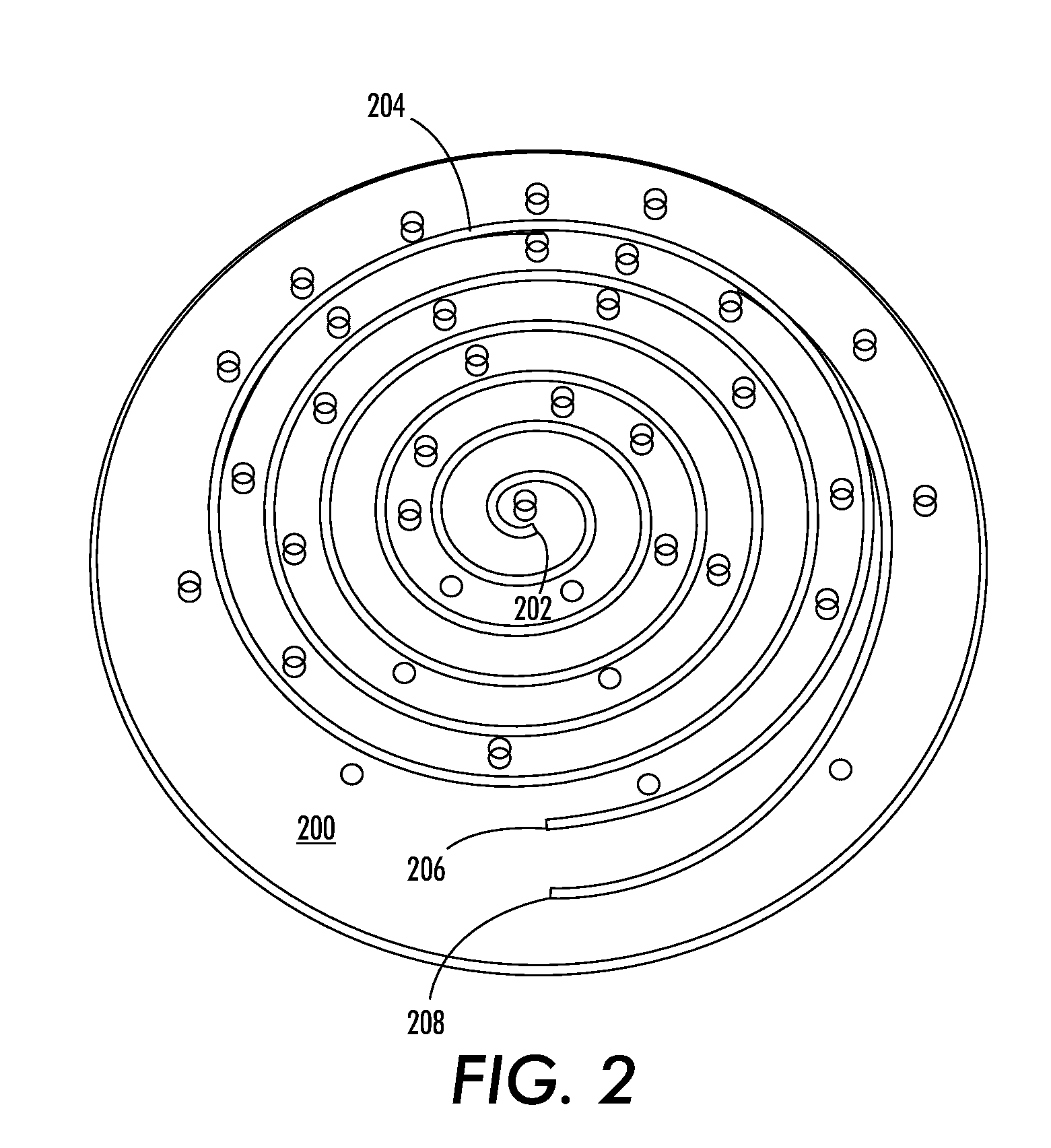
[0013]The presently described embodiments are directed to systems and methods that perform spiral mixing and spiral separation procedures. The spiral mixer includes an apparatus that allows for well-controlled continuous dosing of coagulant (and other known chemicals used in water treatment) into the source water stream just ahead of the spiral device. The relatively narrow confines of the spiral channels in conjunction with turbulent flow conditions allow for a very rapid distribution of the added chemicals, therefore providing an environment that allows the nucleation of very uniform primary aggregates. Further aggregation of these primary aggregates within the channels is limited to dense and compact aggregates due to the (controlled) high shear rate within the confined spaces of the channel. These uniformly-sized aggregated floc particles can then move and readily be separated without the need for downstream sedimentation. The separation can be accomplished with a spiral separat...


PUM

PropertyMeasurementUnit
Lengthaaaaaaaaaa
Timeaaaaaaaaaa
Widthaaaaaaaaaa

Abstract

A system and method for treatment of water. An inlet is operative to receive source water having particles therein. A spiral mixer has a defined spiral channel operative to mix the source water with a coagulant material and an alkalinity material. The spiral mixer is formed to perform in-line coagulation and flocculation processes within the defined spiral channel to form aggregated floc particles. A buffer tank is operative to receive the aggregated floc particles from the spiral mixer. Spiral separator segregates contents of the buffer tank into affluent and waste water that has the aggregated floc particles therein. An outlet is operative to provide a first path for the affluent, and a second path for the waste water having the aggregated floc particles.

Description

CROSS REFERENCE TO RELATED PATENTS AND APPLICATIONS[0001]Cross Reference is hereby made to related patent applications, U.S. patent application Ser. No. [Atty. Dkt. No. 20090576-US-NP), filed [Unknown], by Lean et al., entitled, “Platform Technology For Industrial Separations”; U.S. patent application Ser. No. [20081254-US-NP], filed [Unknown], by Lean et al., entitled, “Stand-Alone Integrated Water Treatment System For Distributed Water Supply To Small Communities”; and U.S. patent application Ser. No. [Atty. Dkt. No. 20080169-US-NP], filed [Unknown], by Lean et al., entitled, “Method and Apparatus For Continuous Flow Membrane-Less Algae Dewatering”, the specifications of which are each incorporated by reference herein in their entirety.BACKGROUND[0002]The core elements of conventional water treatment include the sequential process steps of coagulation, flocculation, sedimentation and physical filtration. These process steps require corresponding physical structures such as coagula...

Claims


Application Information

Patent Timeline
IPC IPC(8): C02F1/52C02F1/66
CPCC02F1/38C02F1/5281C02F1/52C02F9/00C02F2209/44C02F1/66
Inventor LEAN, MENG H.VOLKEL, ARMIN R.KOLE, ASHUTOSHSEO, JEONGGIPAREKH, NITIN S.
Owner PALO ALTO RES CENT INC
Why Eureka
Try Eureka