Power converting circuit and controller thereof
a technology of power conversion circuit and controller, which is applied in the direction of electric variable regulation, process and machine control, instruments, etc., can solve the problems of low conversion efficiency of the controller, failure of the controller con operation, and inability to supply electric power, so as to shorten the life of the controller and ensure the safety of users
- Summary
- Abstract
- Description
- Claims
- Application Information
AI Technical Summary
Benefits of technology
Problems solved by technology
Method used
Image
Examples
first embodiment
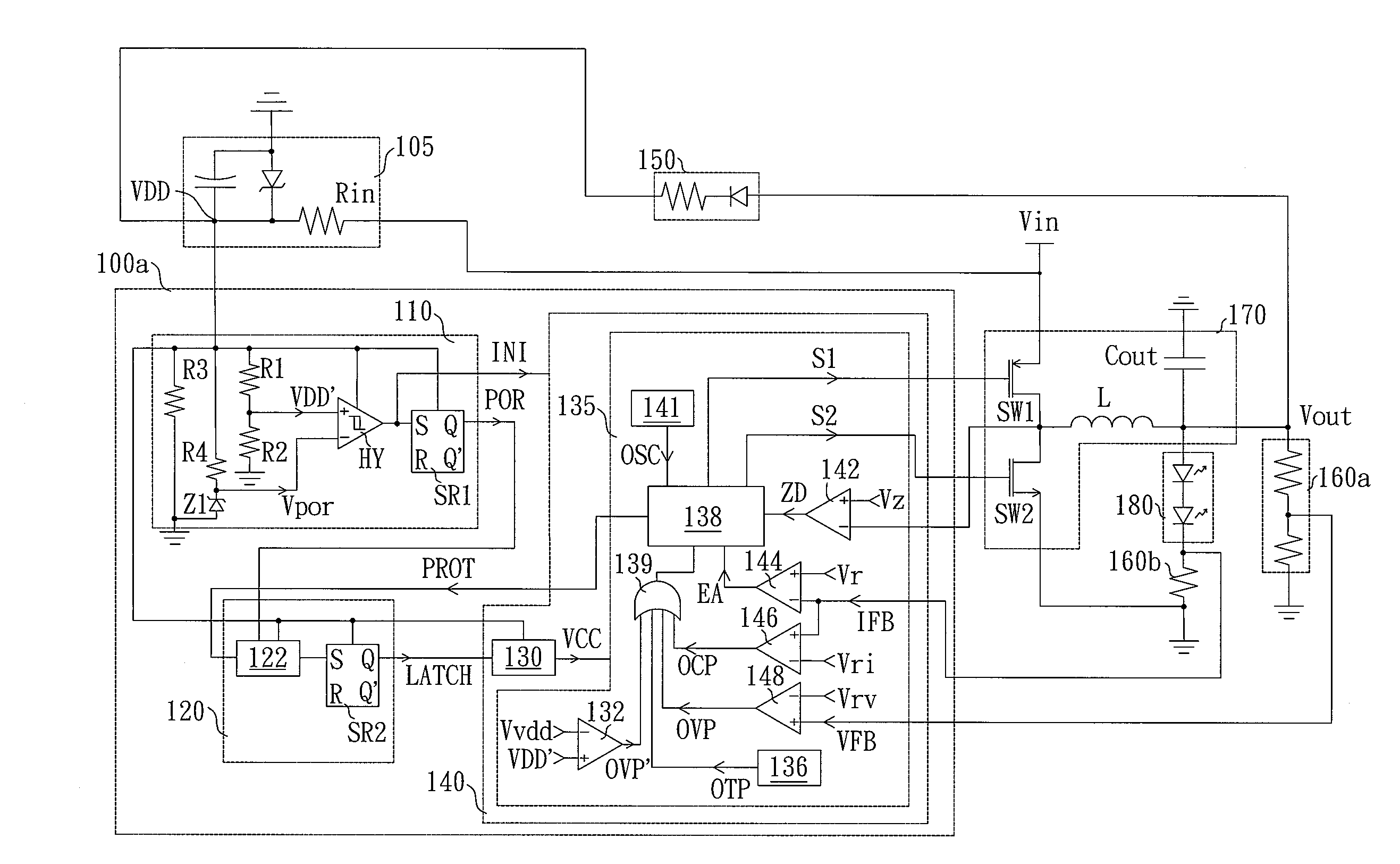
[0028]FIG. 4 is a schematic circuit of a power converting circuit consistent with the present invention. Referring to FIG. 4, the power converting circuit includes a controller 100a, a start circuit 105, a feedback circuit, a converting circuit 170, wherein the feedback circuit includes a first feedback unit 160a and a second feedback unit 160b. The power converting circuit converts an input voltage Vin to an output voltage Vout to drive a light-emitting diode (LED) module 180. The start circuit 105 includes a starting resistor Rin, a capacitor and a Zener diode, wherein the capacitor and the Zener diode are coupled in parallel. One terminal of the start circuit 105 is grounded, and another one of the start circuit 105 is coupled to the input voltage Vin through the starting resistor Rin. Power consumption of the start circuit 105 is adjusted by adjusting the resistance of the starting resistor Rin. Generally, for enhancing efficiency of the power converting circuit, the resistance...
second embodiment
[0034]FIG. 5A and FIG. 5B are schematic circuits of power converting circuits consistent with the present invention. Referring to FIG. 5A and FIG. 5B, the power converting circuit includes a controller, a start circuit 205, a voltage converting device 250, a feedback circuit, a converting circuit 270, wherein the feedback circuit includes a first feedback unit 260a and a second feedback unit 260b. The power converting circuit converts an input voltage Vin to an output voltage Vout to drive a lamp 280. The start circuit 205 includes a capacitor and a Zener diode coupled in parallel and a starting resistor Rin coupled to the input voltage Vin. One terminal of the start circuit 205 is grounded, and another one of the start circuit 205 is coupled to the input voltage Vin through the starting resistor Rin. After the input voltage Vin is inputted to the power converting circuit, the capacitor inside the start circuit 205 starts to store electric power and generates a driving voltage VDD ...
PUM
 Abstract
Description
Claims
Application Information
 - R&D
- Intellectual Property
- Life Sciences
- Materials
- Tech Scout
- Unparalleled Data Quality
- Higher Quality Content
- 60% Fewer Hallucinations
Browse by: Latest US Patents, China's latest patents, Technical Efficacy Thesaurus, Application Domain, Technology Topic, Popular Technical Reports.
© 2025 PatSnap. All rights reserved.Legal|Privacy policy|Modern Slavery Act Transparency Statement|Sitemap|About US| Contact US: help@patsnap.com


