Charging device and charging structure

a charging device and charging structure technology, applied in the direction of electric propulsion mounting, electric devices, transportation and packaging, etc., can solve the problems of increasing the likelihood of short-circuit, and affecting the charging function of the charging device, so as to prevent reduce the possibility of short-circuit and associated problems, and improve the waterproof reliability

Active Publication Date: 2010-12-16
SUBARU CORP
View PDF3 Cites 94 Cited by
  • Summary
  • Abstract
  • Description
  • Claims
  • Application Information

AI Technical Summary

Benefits of technology

[0020]In the charging device according to the present invention, the air nozzle is provided between the plus terminal and the minus terminal forming the power feeding plug so as to blast air radially in an orthogonal direction to the axial direction of the power feeding plug, and therefore the air nozzle can blow away rainwater and the like falling toward the power feeding plug, thereby preventing the power feeding plug from becoming wet.
[0021]In the charging device according to the present invention, at least one air nozzle is provided on the outer side of the power feeding plug, and the air nozzle forms an air curtain that covers the power feeding plug. Therefore, rainwater and the like falling toward the power feeding plug can be blocked by the air curtain, and as a result, the power feeding plug can be prevented from becoming wet.
[0022]The charging structure according to the present invention includes the power receiving connector and the power feeding connector, the air nozzle for preventing the power feeding plug from becoming wet by blasting air is provided in the power feeding connector, the reflux chamber for circulating the air blasted through the air nozzle toward the attachment port of the power receiving connector is provided in the power receiving connector, the operation switch operated when the power feeding connector is attached to the power receiving connector is provided in the power feeding connector, and the air supply is stopped by the controller on the basis of an operation of the operation switch. Therefore, the power feeding plug of the power feeding connector can be prevented from becoming wet while the power feeding connector is attached to the power receiving connector. Further, rainwater or the like adhered to the power receiving plug of the power receiving connector can be blown away by the air blasted through the air

Problems solved by technology

However, when the charging device described in Japanese Patent Application Laid-open No. 1999-122714 (FIG. 1) is used in an outdoor location without a roof or the like, the following problem may occur: when the charging connector is detached from the pole and moved to a vehicle on a rainy day or the like, the charging connector becomes wet unless an operator uses an umbre

Method used


Image

  • Charging device and charging structure
  • Charging device and charging structure
  • Charging device and charging structure

Examples


first embodiment

[0039]the present invention will be described in detail below using the drawings.

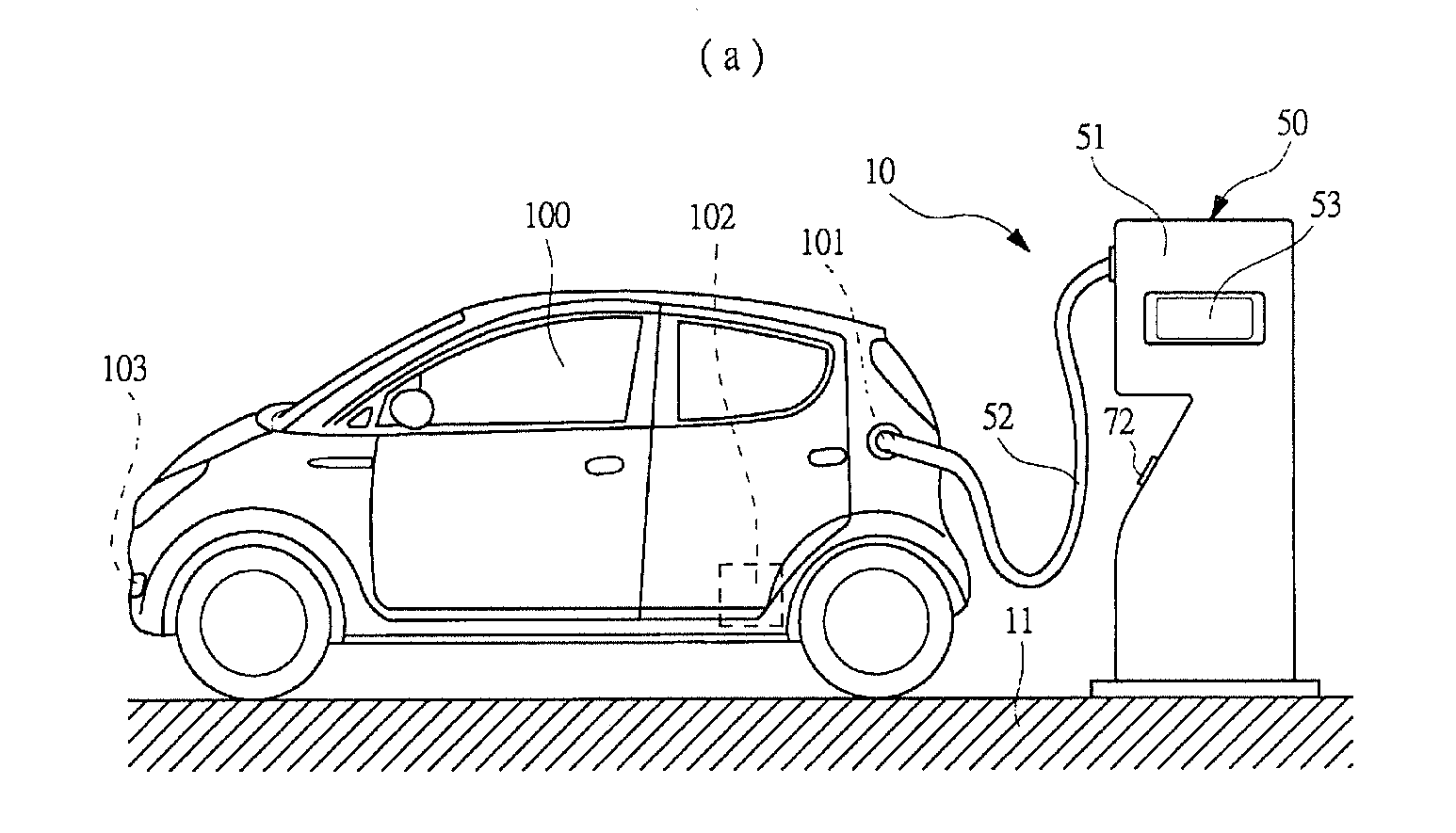
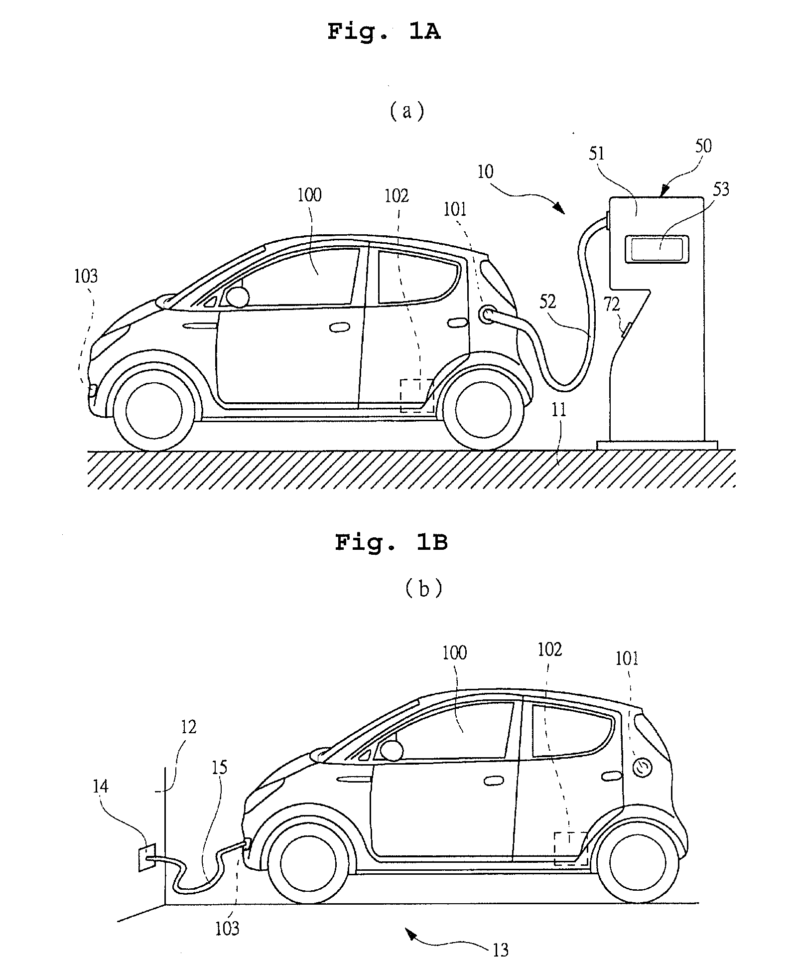
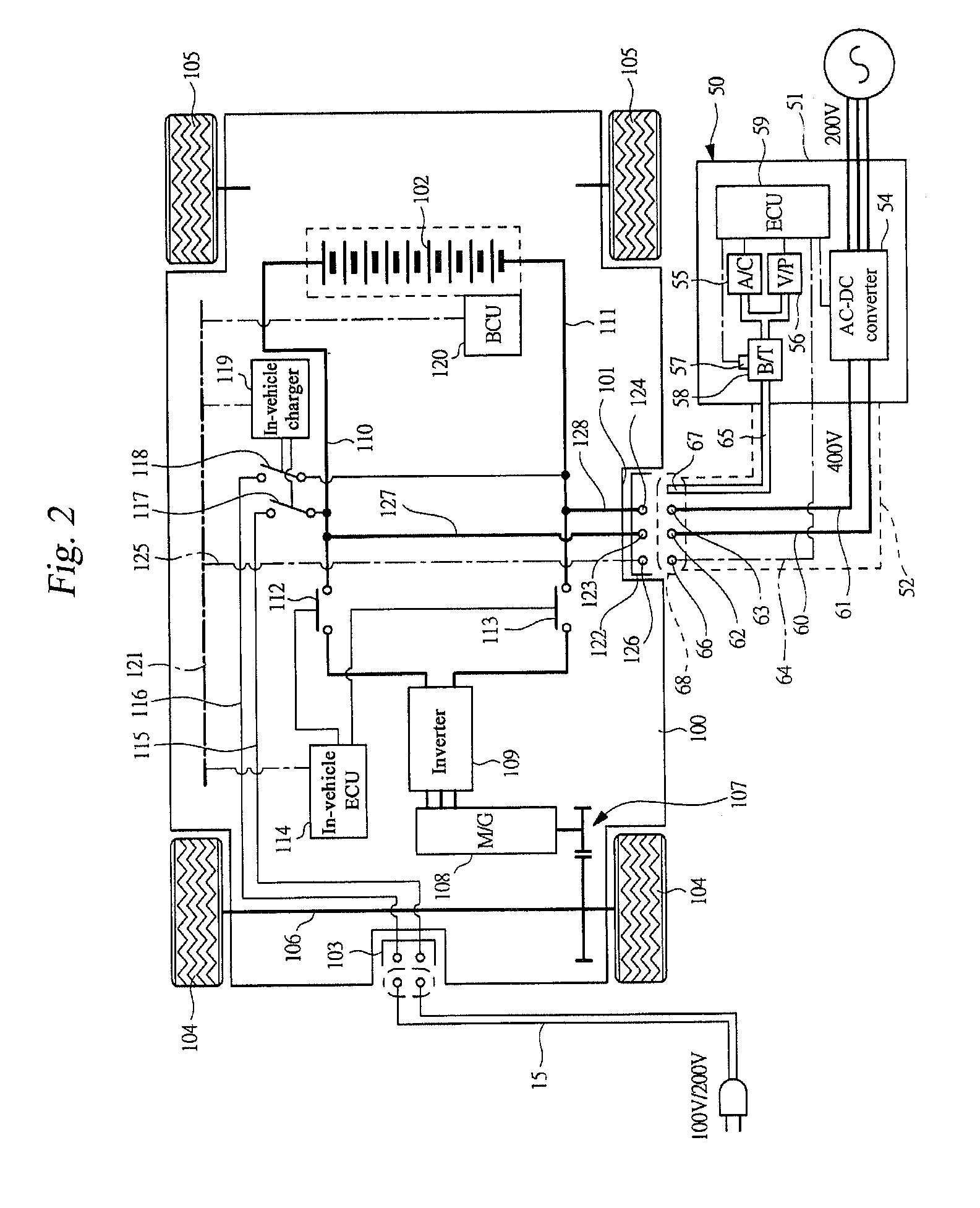
[0040]FIGS. 1A and 1B are illustrative views illustrating charging patterns of an electric vehicle. FIG. 2 is a circuit diagram showing the constitution of an electric system of a charging device and an electric vehicle. FIG. 3 is an external view showing the exterior of the charging device. FIGS. 4A and 4B are enlarged sectional views showing enlargements of a part A indicated in FIG. 3 by a broken line circle. FIG. 5 is a perspective view showing the structure of a power feeding connector and a power receiving connector. FIG. 6 is a pattern diagram showing a charging structure of the charging device. FIG. 7 is an illustrative view illustrating in detail an internal structure of a casing of the charging device.

[0041]FIG. 1A shows a charging pattern of a rapid charging station 10 annexed to an outdoor parking lot (not shown) of a large retail store or the like, in which a plurality of charging devices 5...

third embodiment

[0126]As shown in FIGS. 11A and 11B, the power feeding connector 300 includes the rain guarding cover 301 having a substantially arc-shaped cross-section. The rain guarding cover 301 is formed from a resin material such as plastic, and is capable of moving relative to the power feeding connector 300 in an axial direction thereof, as shown by a solid line arrow in FIG. 11B.

[0127]The single air nozzle 302 is formed integrally with a bottom portion (at the top of the drawings) of the rain guarding cover 301 to extend in the axial direction of the terminals 66, 62 and 63. The air nozzle 302 is provided on the outside of the terminals 66, 62 and 63 and constituted by a hollow pipe formed from an identical material to the rain guarding cover 301. A plurality of communicating holes 303 for blasting air radially in an orthogonal direction (downward in the drawings) to the axial direction of the terminals 66, 62 and 63 are provided on a tip end side of the air nozzle 302. Note, however, tha...

fourth embodiment

[0133]As shown in FIGS. 12A and 12B, the power feeding connector 400 includes the pair of air nozzles 401 extending in the axial direction of the terminals 66, 62 and 63. The air nozzles 401 are provided on the outside of the terminals 66, 62 and 63 so as to sandwich the power feeding connector 400 from the diametrical direction. Respective tip end sides of the air nozzles 401 are provided in positions protruding compared to the tip end side of the power feeding connector 400.

[0134]A plurality of communicating holes 404 for blasting air radially in an orthogonal direction to the axial direction of the terminals 66, 62 and 63 are provided on the tip end side of the respective air nozzles 401. Note, however, that a substantially bell-shaped blowhole (not shown) that opens toward the terminals 66, 62 and 63 may be provided in each air nozzle 401 in place of the plurality of communicating holes 404.

[0135]Air is blasted through the communicating holes 404 in the respective air nozzles 4...


PUM


Abstract

A charging device includes an air nozzle that prevents power-feeding-side terminals from becoming wet by blasting air, fitting switches operated when a power feeding connector is removed from a connector holding portion, and an ECU that activates an air compressor and a vacuum pump on the basis of operations of the fitting switches. The power-feeding-side terminals can be prevented from becoming wet while the power feeding connector is attached to a power receiving connector of an electric vehicle after being removed from the connector holding portion.

Description

CROSS-REFERENCE TO RELATED APPLICATIONS[0001]The disclosure of Japanese Patent Application No. 2009-140742, filed on Jun. 12, 2009 including the specification, drawings and abstract, is incorporated herein by reference in its entirety.BACKGROUND OF THE INVENTION[0002]1. Field of the Invention[0003]The present invention relates to charging devices and charging structures for charging secondary batteries installed in a vehicle.[0004]2. Description of the Related Art[0005]Vehicles that are driven using an electric motor include electric vehicles (EV) that employ only an electric motor as a drive source and hybrid electric vehicles (HEV) having both an electric motor and an engine as drive sources. An in-vehicle battery (secondary battery) is installed in both types of vehicle to supply power to the electric motor, and when a state of charge of the in-vehicle battery decreases, the in-vehicle battery must be charged using a household commercial power supply or a charging device provided...

Claims


Application Information

Patent Timeline
IPC IPC(8): H02J7/00
CPCY02T10/7005Y02T90/121Y02T90/127Y02T90/128Y02T90/14B60L53/11Y02T10/7072B60L53/16B60L53/20B60L53/30B60L53/31B60L2200/26Y02T10/70Y02T90/12
Inventor SAKURAI, MASATO
Owner SUBARU CORP
Why Eureka
Try Eureka