Optical system for a Light Emitting Diode with collection, conduction, phosphor directing, and output means

Inactive Publication Date: 2010-12-16
RAMBUS DELAWARE
View PDF93 Cites 19 Cited by
  • Summary
  • Abstract
  • Description
  • Claims
  • Application Information

AI Technical Summary

Benefits of technology

[0008]The present invention is an optical system that is used to create white light from a package that is mechanically similar to a conventional light bulb. The system efficiently directs blue light from an LE

Problems solved by technology

One of the problems inherent in the use of LEDs for general lighting is the creation of white light from the narrow wavelength of light that is generated by an LED.
Some of th

Method used


Image

  • Optical system for a Light Emitting Diode with collection, conduction, phosphor directing, and output means
  • Optical system for a Light Emitting Diode with collection, conduction, phosphor directing, and output means
  • Optical system for a Light Emitting Diode with collection, conduction, phosphor directing, and output means

Examples


Embodiment Construction

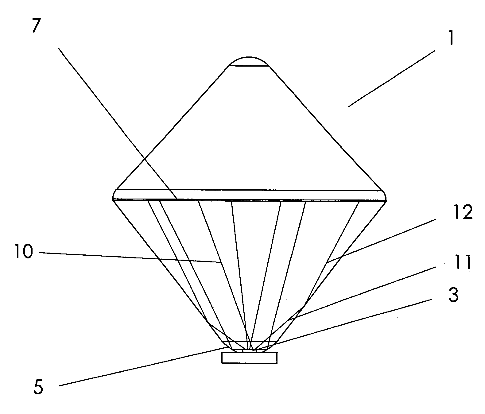
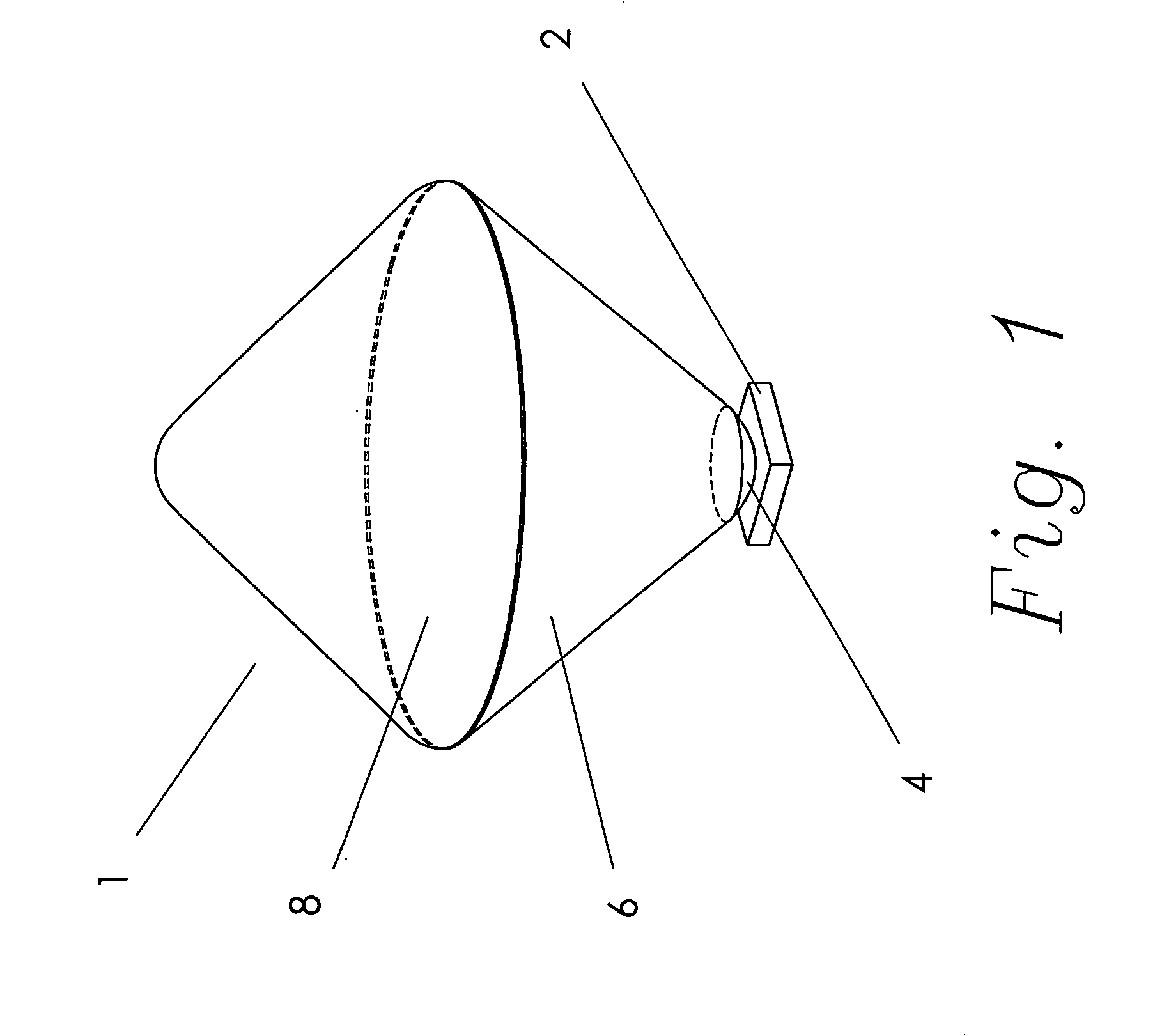
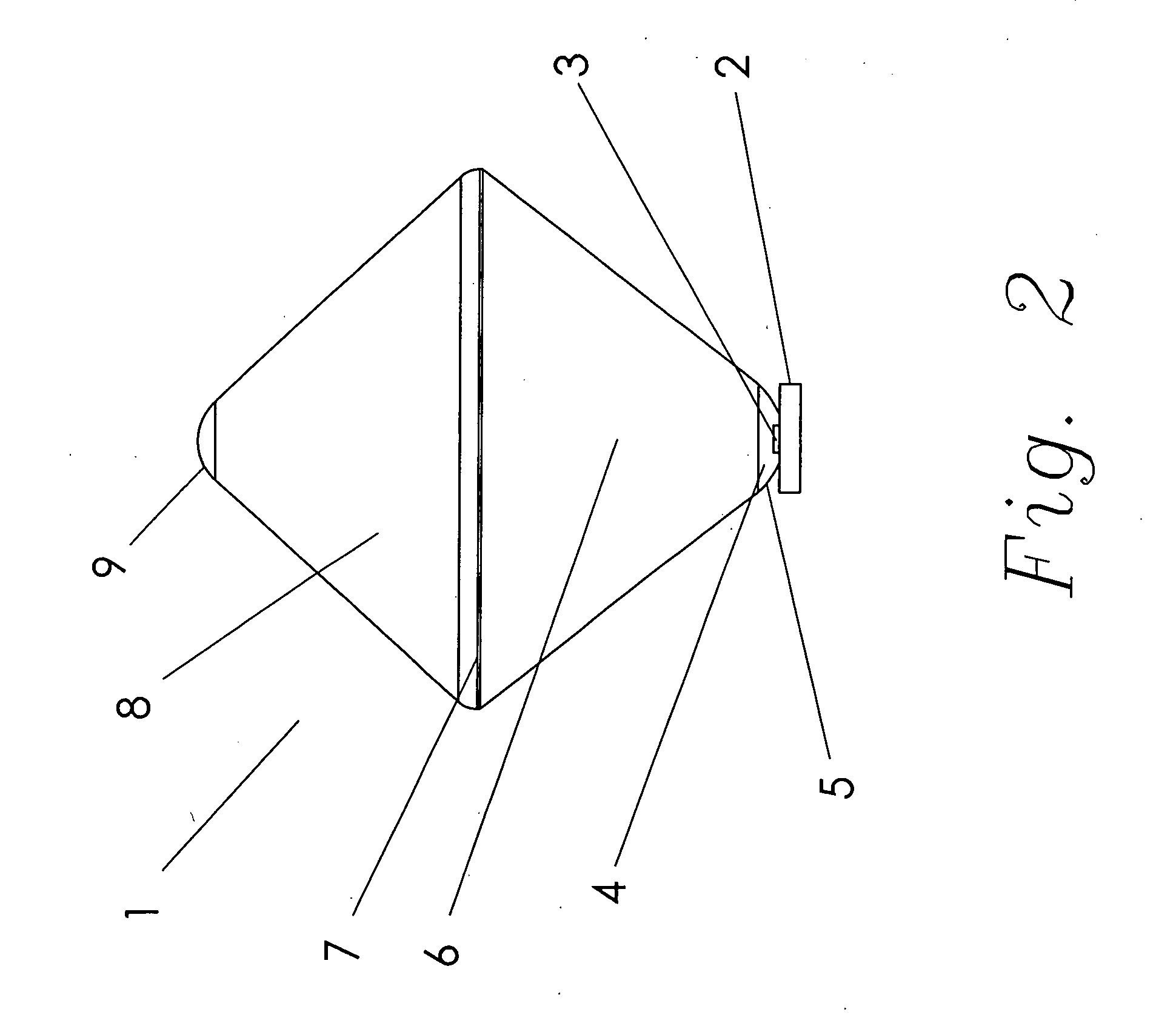
[0019]Referring first to FIGS. 1 and 2, the optical system 1 of the present invention comprises a main body made from a base 6 and an upper conical cap 8. The main body of the optical system 1 is generally diamond shaped, with rounded point ends. The base 6 has generally the shape of an inverted cone. The cap 8 is also generally conical, but with a rounded base. The upper end 9 of the cap 8 and the lower end of the base 6 are both shown with a radius terminal area. The radius tips are not included for performance factors, but rather are included to eliminate sharp points that could injure the user. The rounded areas are for safety, not performance, reasons.

[0020]A light source, LED 3, is mounted on a PCB 2. The PCB 2 is chosen simply as a convenient method for mounting and supplying power to an LED 3. There are other materials and methods that could be used to supply power to the LED 3 that are known to those skilled in the art. The specific electronic circuitry used to power the sy...


PUM


Abstract

An optical system with an LED light source utilizes a base with an inverted conical shape to conduct light to a phosphor layer. The phosphor layer emits light from both upper and lower surfaces. The base and a substantially mirror image cap element facilitate efficient extraction of the phosphor-generated light from the optical system so that the output of the system is omni-directional light suitable for common lighting applications. The system is very efficient in that nearly all the light generated by the LED is transmitted to the phosphor layer, and nearly all the light emitted from the phosphor layer is output from the system.

Description

FIELD OF THE INVENTION[0001]This invention relates generally to extraction and control of light from a light emitting diode, LED, and more particularly is an optical system to improve the extraction of light from an LED, the direction of the light to a phosphor source, and the omni-directional extraction from the system of the light generated by the phosphor. The optical system directs the output light in a pattern that is similar to that of a conventional incandescent light bulb.BACKGROUND OF THE INVENTION[0002]Numerous products require an efficient source of white light that is omnidirectional. In many applications, the desired output would be similar to the output of a conventional light bulb, the breakthrough invention of Thomas Edison, U.S. Pat. No. 223,898, issued Jan. 27, 1880. A host of products has been designed around the output taught by this historic invention. Recently, fluorescent-based light bulbs have been developed to mimic the output of the Edison bulb. Many invent...

Claims


Application Information

Patent Timeline
IPC IPC(8): F21V9/16
CPCF21V7/0091F21V13/04H01L33/507F21V9/30H01L33/58F21Y2115/10F21K9/68H01L33/54F21V9/06F21V13/08H01L33/50
Inventor RICHARDSON, BRIAN EDWARD
Owner RAMBUS DELAWARE
Why Eureka
Try Eureka