Cooling System for a Computer Server Cabinet in a Data Center

a cooling system and data center technology, applied in ventilation systems, electrical apparatus casings/cabinets/drawers, domestic cooling apparatus, etc., can solve the problems of no mechanism to ensure, no mechanism to prevent, and significant amount of energy wasted in moving excess air

Inactive Publication Date: 2010-12-16
BLACKROCK
View PDF62 Cites 108 Cited by
  • Summary
  • Abstract
  • Description
  • Claims
  • Application Information

AI Technical Summary

Problems solved by technology

A significant amount of energy is wasted in moving excess volumes of air.
Without containment, there is no mechanism to ensure that all of the cold air generated by the CRACs reaches the equipment racks where it can be used for cooling, nor is there a mechanism to prevent hot air from flowing into the equipment input.
As a result, the amount of heat that can be transferred from the equipment housed within each cabinet is limited.
Although this method adequately provides the required cooling, it is costly and relies on the use of additional fans, which can add inefficiencies into the cooling system.
This method is costly and takes up valuable rack space within the data center.
Chilled water units require water piping to be installed under the floor, and the small fans have lower mechanical efficiency than the large CRAC units.
Both types of local cooling solutions require an expensive and intrusive piping system to be installed within the data center.
Both methods rely on external fans which consume energy and are prone to failure.
Chilled water fan-coils also require expensive piping and may expose the equipment to the risk of water contact.
Further, these systems do not provide the redundancy of multiple cooling air sources.
These systems allow for efficient cooling at the expense of a loss of flexibility.
As a result, these systems are generally only applicable to new builds.
Each of the methods mentioned above are expensive to purchase, install, and operate.
These methods introduce complexity and additional points of failure to the critical cooling systems within a data center.

Method used


Image

  • Cooling System for a Computer Server Cabinet in a Data Center
  • Cooling System for a Computer Server Cabinet in a Data Center
  • Cooling System for a Computer Server Cabinet in a Data Center

Examples


Embodiment Construction

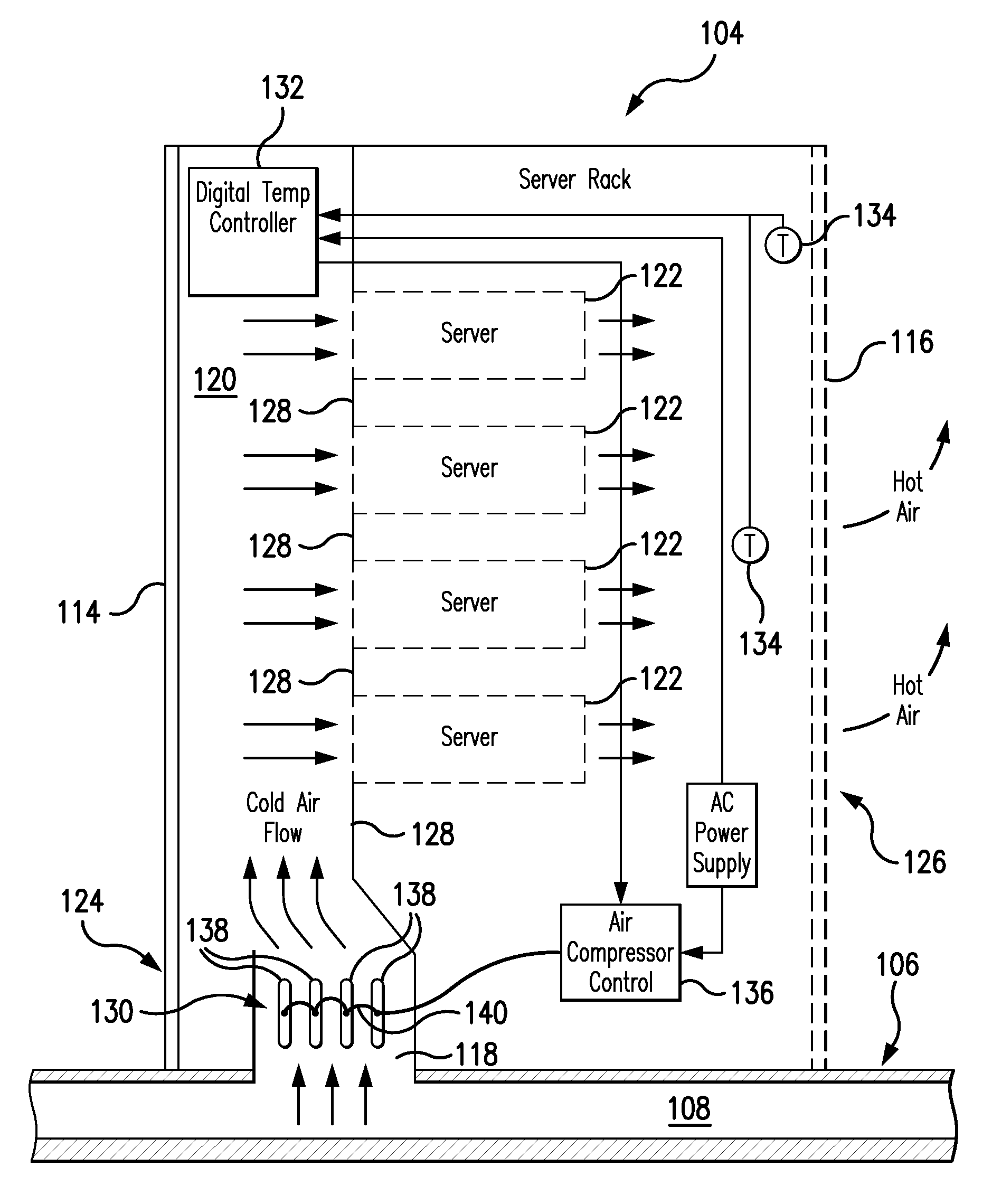
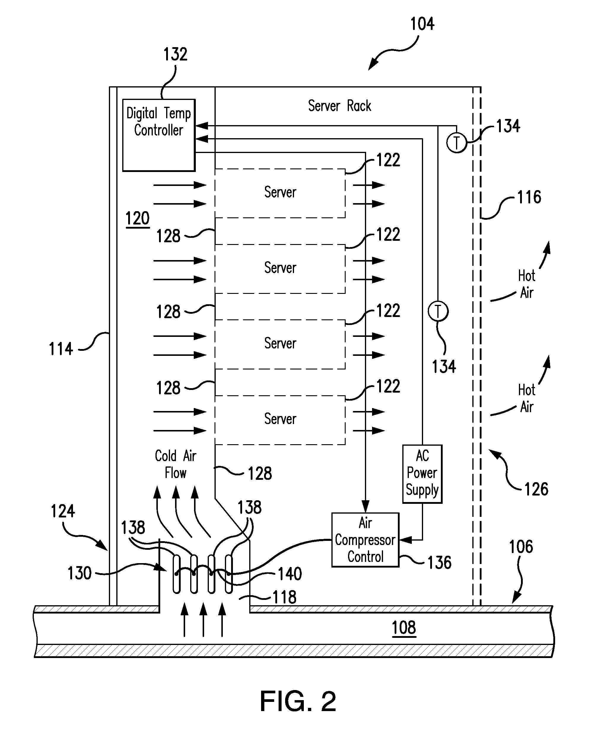
[0029]Reference will now be made in detail to the present preferred embodiments of the systems and methods for cooling computer equipment in a data center. In one exemplary embodiment, the system comprises a computer server cabinet housing a plurality of servers mounted within the cabinet on a plurality of racks. Although servers and server cabinets are referenced throughout this disclosure, it should be understood that the systems and methods of the present disclosure may be applied to the cooling of other types of equipment and in other types of applications.

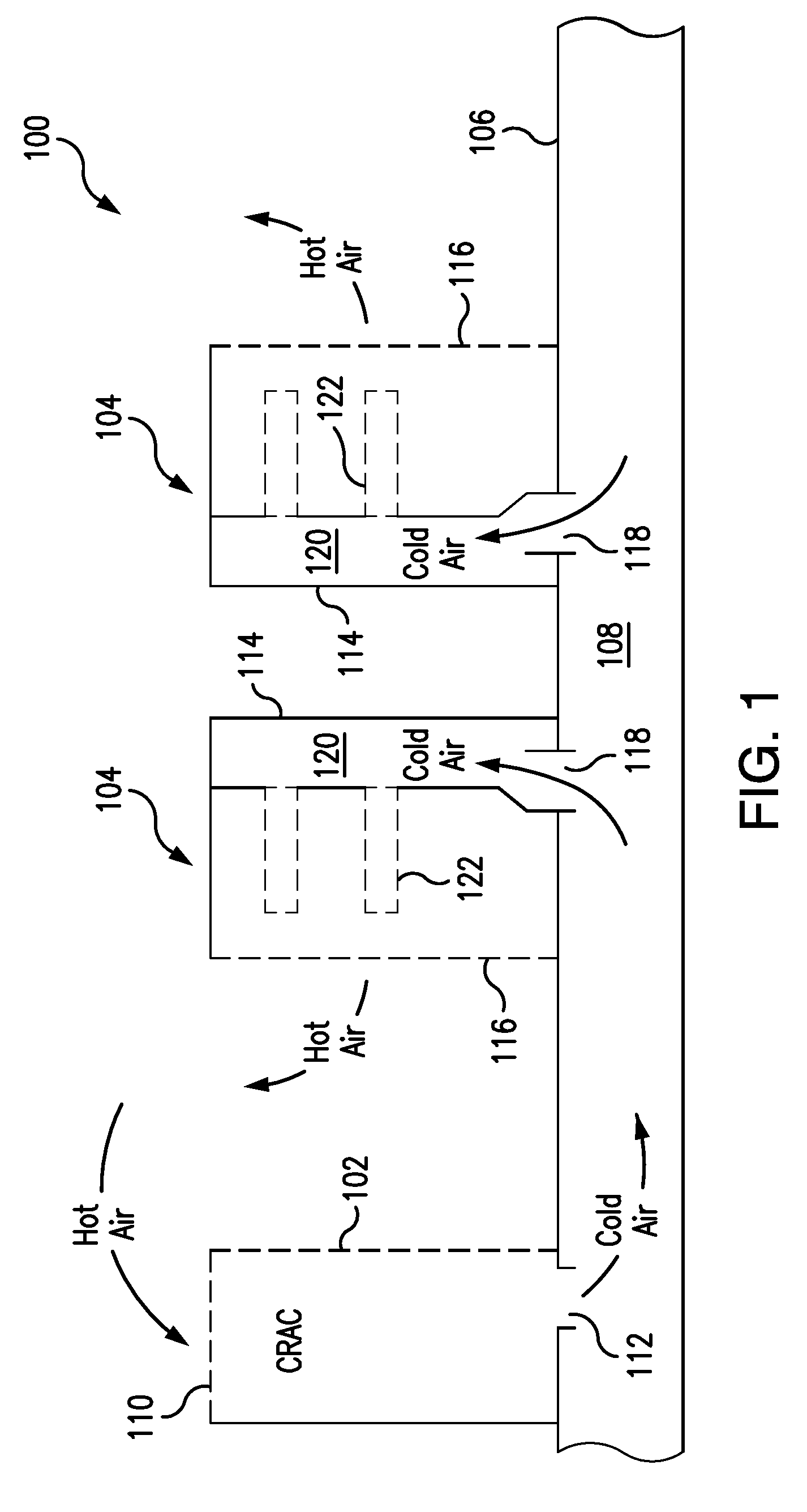
[0030]For purposes of explanation and illustration, and not limitation, an exemplary embodiment of a cooling system in accordance with the present invention is shown in FIG. 1 and designated generally by the reference numeral 100. Cooling system 100 includes at least one Computer Room Air Conditioner (CRAC) 102, and at least one server cabinet 104. CRAC 102 and server cabinet 104 are positioned on a raised floor 106 that defin...


PUM


Abstract

A system for cooling computer equipment in a data center. The system includes a raised floor defining a pressurized under-floor plenum; a computer room air conditioning unit disposed on the raised floor and having a hot air inlet and a cold air outlet, wherein the cold air outlet is in fluid communication with pressurized under-floor plenum; and a server cabinet housing server equipment and including a pressurized vertical plenum in fluid communication with under-floor plenum via an inlet duct. The server cabinet is configured to receive a cold air stream from the under-floor plenum via the inlet duct into the vertical plenum and draw the cold air across the server equipment to provide cooling without the use of external fans. The system may also include an inflatable airfoil damper assembly disposed within the inlet duct and configured to provide failsafe variable airflow to the vertical plenum within the server cabinet.

Description

CROSS REFERENCE TO RELATED APPLICATION[0001]This application claims priority to U.S. Provisional Patent Application No. 61 / 185,861, filed Jun. 10, 2009, the disclosure of which is incorporated herein by reference in its entirety.BACKGROUND OF THE INVENTION[0002]1. Field of the Invention[0003]The present invention is directed to environmental control of data centers. More specifically, the present invention involves systems and methods for directly and efficiently cooling information technology equipment housed within a cabinet in a data center.[0004]2. Background of the Related Art[0005]A typical data center consists of a climate-controlled room with rows of equipment racks housed within cabinets and arranged on a raised floor. Equipment housed within the cabinets may include servers and other electronic devices. Computer Room Air Conditioners (CRACs) collect hot air from the room and deliver cold, pressurized air to a plenum created below the raised floor. The raised floor typicall...

Claims


Application Information

Patent Timeline
Patent Type & Authority Applications(United States)
IPC IPC(8): H05K5/02F24F13/10F25D9/00
CPCH05K7/20836F24F11/0001H05K7/20736
Inventor NOVICK, BARRY
Owner BLACKROCK
Why Eureka
Try Eureka