Broadcast service signal transmission method and transmission device

a technology of transmission device and broadcast service, which is applied in the direction of transmission, electrical apparatus, synchronisation arrangement, etc., can solve the problems of affecting the transmission efficiency of the mobile terminal, etc., and achieves good efficiency.

Inactive Publication Date: 2010-12-16
FUJITSU LTD
View PDF4 Cites 26 Cited by
  • Summary
  • Abstract
  • Description
  • Claims
  • Application Information

AI Technical Summary

Benefits of technology

[0012]Taking the aforementioned problems into consideration, one object of the present invention is to make it possible for a mobile terminal in a high-speed moving body in which a plurality of users are riding to properly receive data from a base station, and make it possible for the base station to transmit data with good efficiency.

Problems solved by technology

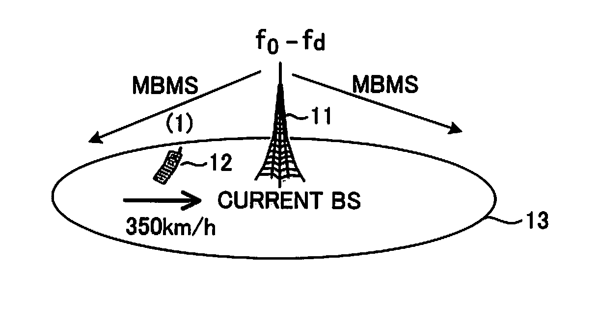
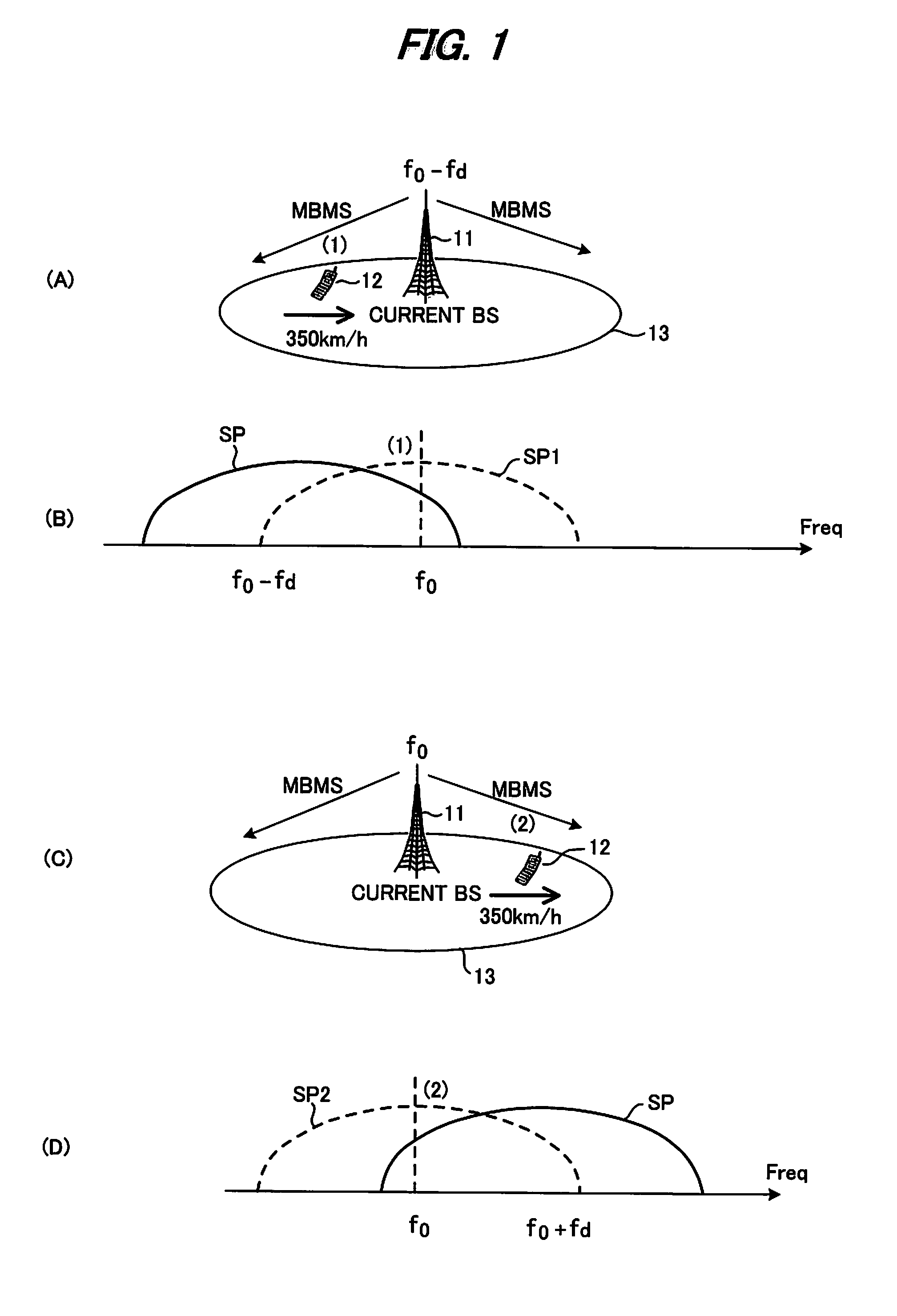
Therefore, the reception power of frequency f0 at the mobile terminal decreases, and Doppler distortion occurs making good reception impossible.
However, the conventional methods, AFC (Automatic Frequency Control) or high-performance channel estimation, for correcting this Doppler distortion had the following problems.
As a prerequisite for being able to apply the conventional AFC, it is necessary to monitor channel states on the radio regularly to estimate their changed frequency, and by changing the communication method, it has become very difficult to compensate for Doppler distortion with AFC technology.
Therefore, this conventional art has a problem in that controlling whether to transmit a radio signal having frequency on the increasing side or frequency on the decreasing side is complicated.
Moreover, this conventional art is transmission control that takes into consideration Doppler shifting of transmission from a mobile station to a base station, and is not transmission control for the base station that takes into consideration the speed of movement of the moving body.
In other words, the conventional art is not intended to make it possible for a moving body to properly receive a signal from a base station when Doppler shifting occurs.
Furthermore, the aforementioned conventional art has a problem in that a GPS receiver must be provided in the moving body, which increases the cost of the moving body.

Method used


Image

  • Broadcast service signal transmission method and transmission device
  • Broadcast service signal transmission method and transmission device
  • Broadcast service signal transmission method and transmission device

Examples


embodiment 5

(e) Summary of Embodiment 5

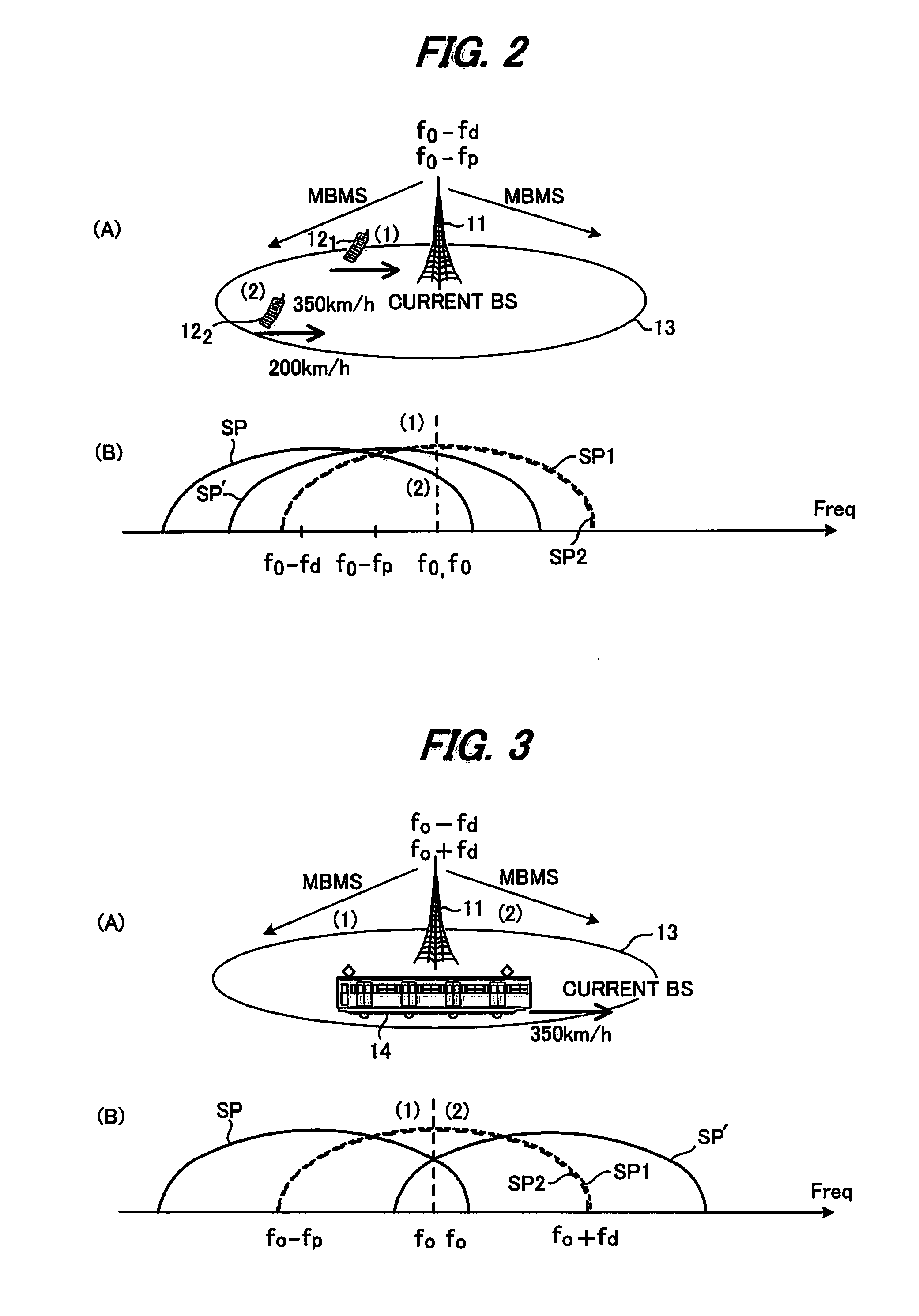
[0060]FIG. 5 is a diagram for explaining a fifth embodiment, where the same reference numbers are used for parts that are the same as those in FIG. 3. In FIG. 5, only when a moving body 14 that is moving at high speed is inside a cell 13, the base station 11 transmits a broadcast service MBMS radio signal using a plurality of radio signals having frequencies f0−fd and f0+fd other than the original radio frequency f0, and at other times, transmits a MBMS radio signal using only the radio frequency f0. In other words, in the fifth embodiment, control is performed so that the frequency of the broadcast service is adaptively assigned. As a method for accomplishing this, the time of passing of the moving body 14 and the estimated passing speed are notified from a position information management server 21, and adaptive control is performed according to that information. For example, a server that performs diagram management of the train is used as the position i...

embodiment 1

Second Variation of Embodiment 1

[0067]FIG. 7 is a diagram of the construction of a transmission device that makes it possible to constantly provide a broadcast service MBMS to a moving terminal that is moving at a speed equal to or less than a reference speed, where a frequency conversion unit 39 and combination unit 40 are added to the construction of FIG. 6.

[0068]In the transmission device of FIG. 7, the frequency conversion unit 39 constantly converts the baseband signal resulting from modulation to a radio signal having the original frequency f0 and outputs the result, and only when there is a moving body in a cell that is moving at a high speed higher than the reference speed, the frequency conversion / shifting unit 33 convert the baseband signal resulting from modulation to a radio signal having a frequency of f0−fd and output the result. The combination unit 40 combines the radio signal having a frequency f0 that is output from the frequency conversion unit 39 with the radio s...

embodiment 2

(C) Embodiment 2

[0070]FIG. 9 is a diagram of the construction of a transmission device in a base station of a second embodiment, where the same reference numbers are used for parts that are the same as those of the first embodiment in FIG. 6. This embodiment differs in that two frequency conversion / shifting units 331, 332 and a combination unit 41 are provided so that a broadcast service MBMS can be provided to two high-speed moving bodies that are moving at different speeds.

[0071]The position information server 51 sends information to the transmission device of the base station indicating whether there is a moving body in a cell that is moving at a high speed higher than a reference speed (for example, a train), and when there is such a high-speed moving body, sends information to the transmission device of the base station indicating the movement speed and whether the moving body is moving toward the base station or moving away from the base station. In this case, when there are t...


PUM


Abstract

When a transmission device transmits a broadcast service signal using a radio signal, the transmission device determines whether there is a moving body that is moving at high speed toward or away from the transmission device, and calculates the amount of Doppler shift of a radio frequency due to high speed movement based on the movement speed of the moving body when there is such a high-speed moving body. Moreover, the transmission device shifts the frequency of the radio signal for transmitting the broadcast service signal by the Doppler shift amount in the opposite direction of Doppler shift direction. By doing so, it is possible for a moving terminal to receive the broadcast service signal from the original radio frequency regardless of Doppler shifting.

Description

CROSS REFERENCE TO RELATED APPLICATION[0001]This application is a continuation of PCT application of PCT / JP2008 / 053762, which was filed on Mar. 3, 2008, now pending, the contents of which are herein wholly incorporated.BACKGROUND OF THE INVENTION[0002]The present invention relates to a broadcast service signal transmission method and transmission device, and more particularly to a broadcast signal transmission method and transmission device that transmits a broadcast service signal using radio transmission.[0003]In mobile communication, when a moving body is moving at high speed, a phenomenon occurs in that the spectrum shifts due to Doppler effect. Particularly, when in the mountains or inside a tunnel there are hardly any reflected waves, so only the radio signal propagates toward the moving body making it easy for Ricean distribution to occur. Conventionally, in conditions where Doppler shift due to Ricean distribution occurred, AFC (Automatic Frequency Control) or high-performan...

Claims


Application Information

Patent Timeline
Patent Type & Authority Applications(United States)
IPC IPC(8): H04B15/00
CPCH04W56/0035
Inventor YOKOYAMA, HITOSHI
Owner FUJITSU LTD
Why Eureka
Try Eureka