In-field configuration of land survey sensors

a technology of in-field configuration and land survey, applied in the direction of seismic data acquisition, instruments, using reradiation, etc., can solve the problems of preventing the placement of sensors, preventing the deployment of sensors, and affecting the practicality of digging

Active Publication Date: 2010-12-16
WESTERNGECO LLC
View PDF20 Cites 5 Cited by
  • Summary
  • Abstract
  • Description
  • Claims
  • Application Information

AI Technical Summary

Benefits of technology

[0010]Described herein are implementations of various technologies for a method for in-field configuration of land survey sensors. In one implementation, one or more planned positions of the sensors may be received. One or more actual positions of the sensors be determined. The actual positions may be sent to the sensors while the sensors are powered off.
[0011]In another implementation, a plurality of sensors may be disposed in a survey area. A handheld device may be used for configuring the sensors. The handheld device may receive one or more planned positions of the sensors. The handheld device may determine one or more actual positions of the sensors. Further, the handheld device may send the actual positions to the sensors while the sensors are powered off.
[0012]In another implementation, seismic data may be received from one or more sensors in a survey area. The actual positions of the sensors may be received. The seismic data may be processed based on the actual positions.
[0013]The claimed subject matter is not limited to implementations that solve any or all of the noted disadvantages. Further, the summary section is provided to introduce a selection of concepts in a simplified form that are further described below in the detailed description section. The summary section is not intended to identify key features or essential features of the claimed subject matter, nor is it intended to be used to limit the scope of the claimed subject matter.

Problems solved by technology

In some circumstances, conditions on the ground may prevent the placement of a sensor at the planned coordinates.
Further, soil conditions at the planned coordinates may impede sensor deployment.
For example, rocky soil at the planned coordinates may make digging impractical.
As such, placing the sensors in locations other than the planned coordinates may introduce errors into the processing and the images produced therefrom.

Method used


Image

  • In-field configuration of land survey sensors
  • In-field configuration of land survey sensors
  • In-field configuration of land survey sensors

Examples


Embodiment Construction

[0021]The discussion below is directed to certain specific implementations. It is to be understood that the discussion below is only for the purpose of enabling a person with ordinary skill in the art to make and use any subject matter defined now or later by the patent “claims” found in any issued patent herein.

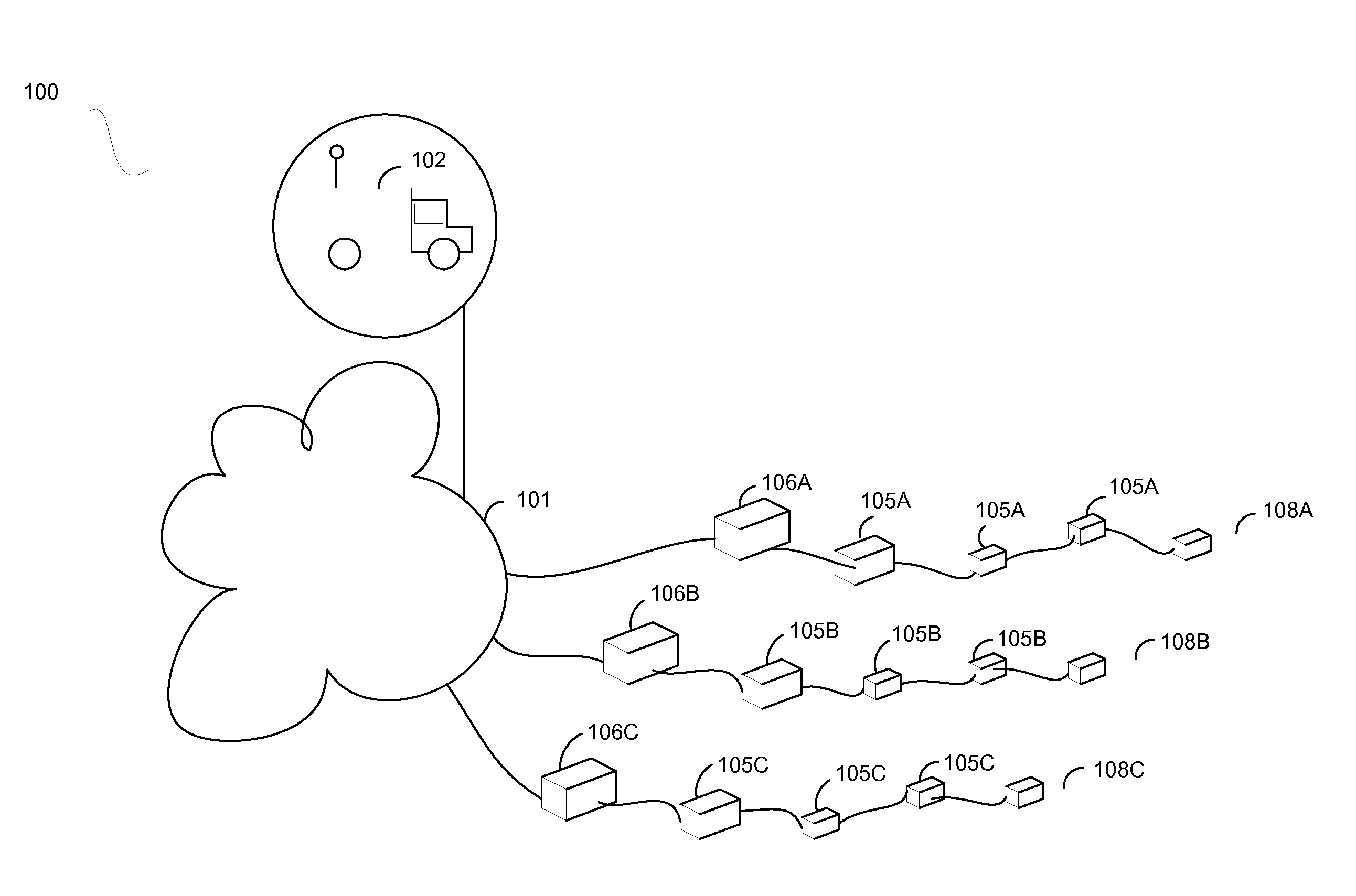
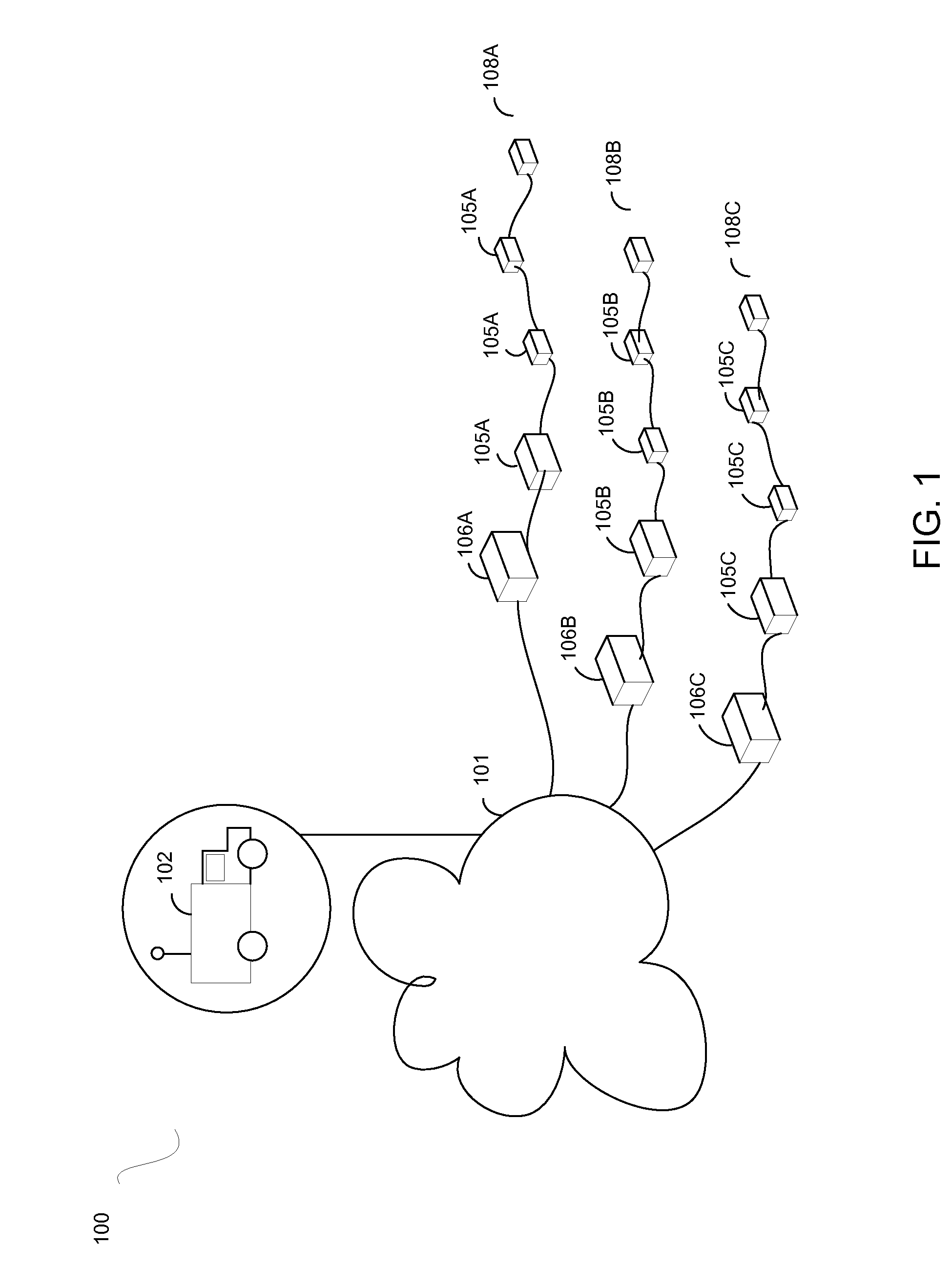
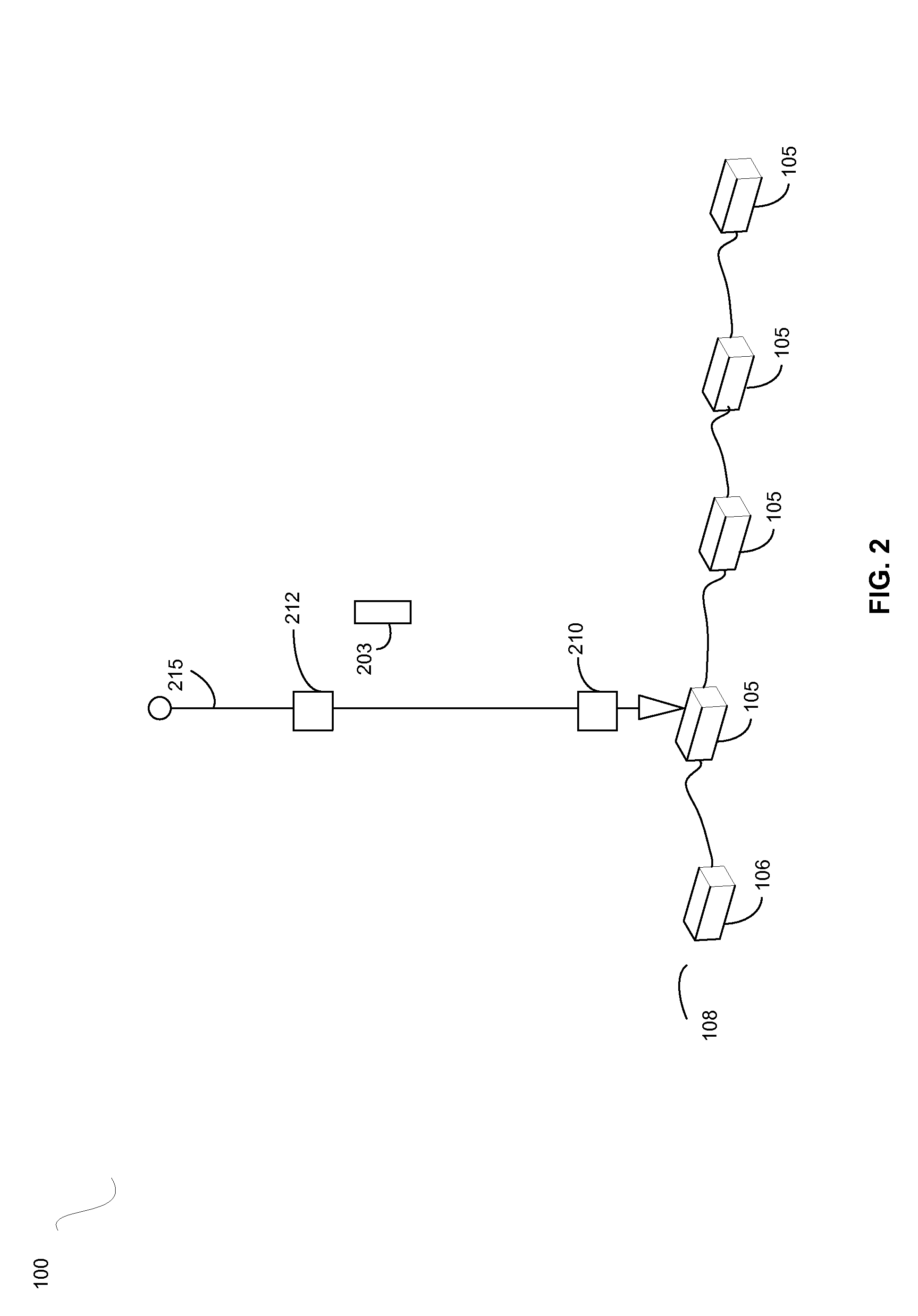
[0022]The following paragraph provides a brief summary of various techniques described herein. In general, a set of coordinates for positioning land survey sensors may be downloaded to a handheld device. A survey crew may place the sensors according to the downloaded coordinates. In some circumstances, the sensors may be placed in positions different than, but near to, the planned positions. After placing the sensor, the survey crew may determine the actual coordinates of the placed sensor by using a global navigation satellite system device. The coordinates may be written to a radio frequency identification (RFID) tag in the sensor. After the survey is conducted, the coordi...


PUM


Abstract

Described herein are implementations of various technologies for a method for in-field configuration of land survey sensors. One or more planned positions of the sensors may be received. One or more actual positions of the sensors be determined. The actual positions may be sent to the sensors while the sensors are powered off.

Description

BACKGROUND[0001]1. Field of the Invention[0002]Implementations of various technologies described herein generally relate to methods and systems for configuring land survey sensors.[0003]2. Description of the Related Art[0004]The following descriptions and examples are not admitted to be prior art by virtue of their inclusion within this section.[0005]Typically, land surveys may be performed for the purpose of geotechnical projects, such as hydrocarbon exploration. Land survey sensors may be deployed in the area to be surveyed based on a plan devised by a geophysicist. The initial plan may simply describe a pattern within which the sensors are to be placed. The pattern usually describes the relationships of sensors to each other in the deployment. These relationships may describe vertical and horizontal distances between individual sensors and / or rows of sensors.[0006]Once the pattern is devised, a survey team may identify coordinates within the survey area where the sensors can be d...

Claims


Application Information

Patent Timeline
Patent Type & Authority Applications(United States)
IPC IPC(8): G01V1/28G01S1/00G06F15/00
CPCG01C15/00G01V1/003G01S13/825G01S5/0027
Inventor GOLPARIAN, DANIELLEPPER, JOHN
Owner WESTERNGECO LLC
Why Eureka
Try Eureka