Transmission
a technology of transmission and transmission shaft, which is applied in the direction of gearing details, transportation and packaging, gearing, etc., can solve the problems of affecting the driving and fuel efficiency of the vehicle, the loss of driving power of the transmission shaft, etc., and achieves the reduction of cost and weight, the effect of reducing the total resistance acting on the plurality of gears during agitation of lubrication oil, and enhancing the transmission power transmission efficiency
- Summary
- Abstract
- Description
- Claims
- Application Information
AI Technical Summary
Benefits of technology
Problems solved by technology
Method used
Image

Examples
first embodiment
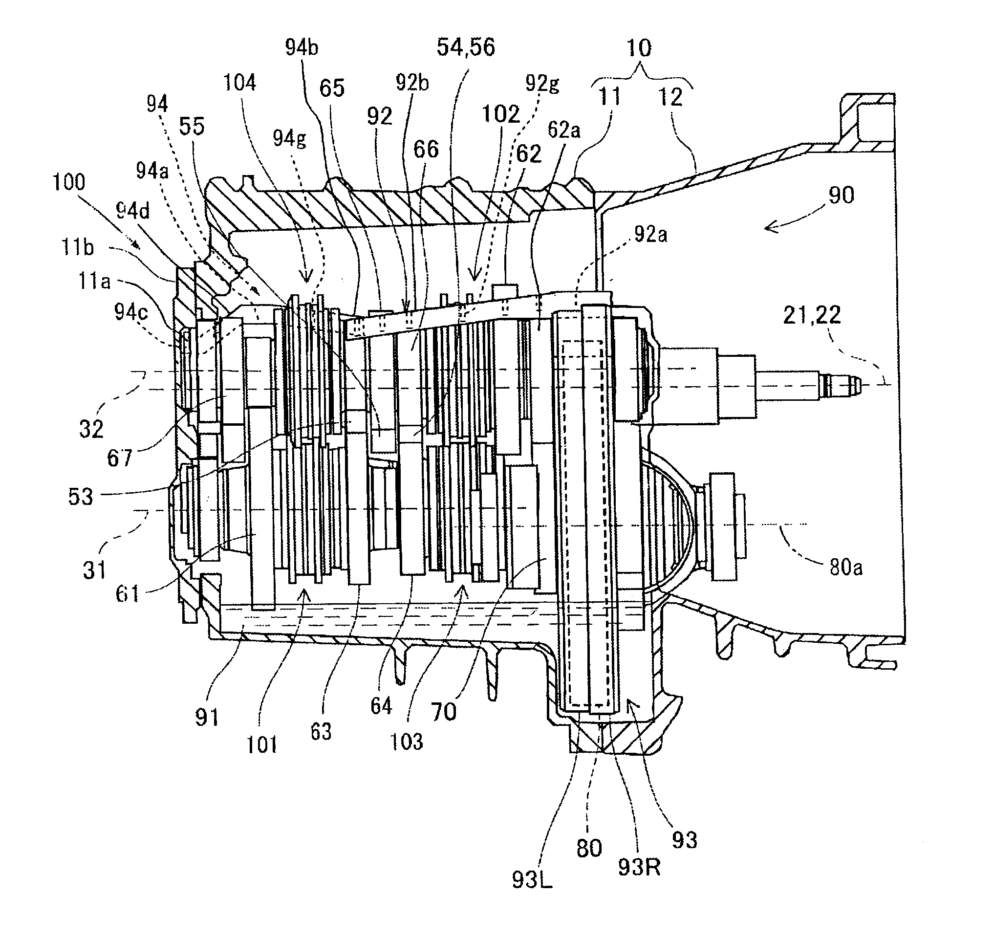
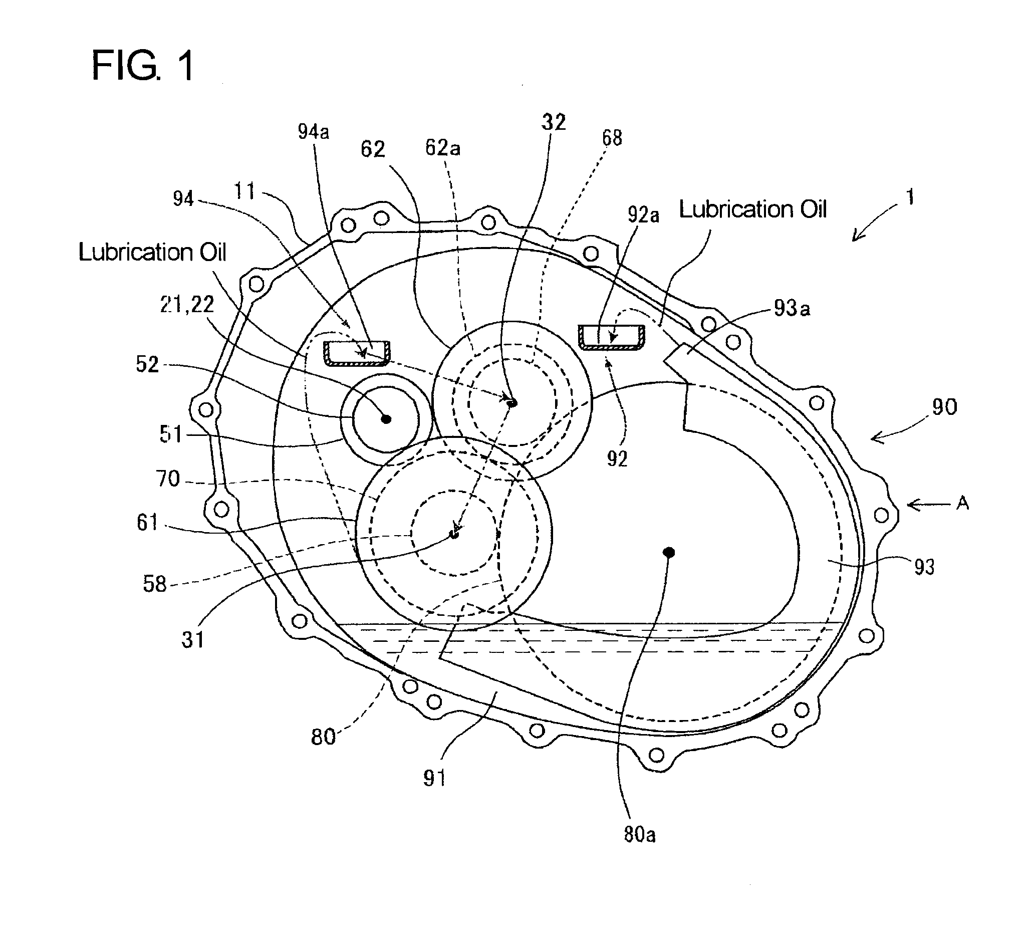
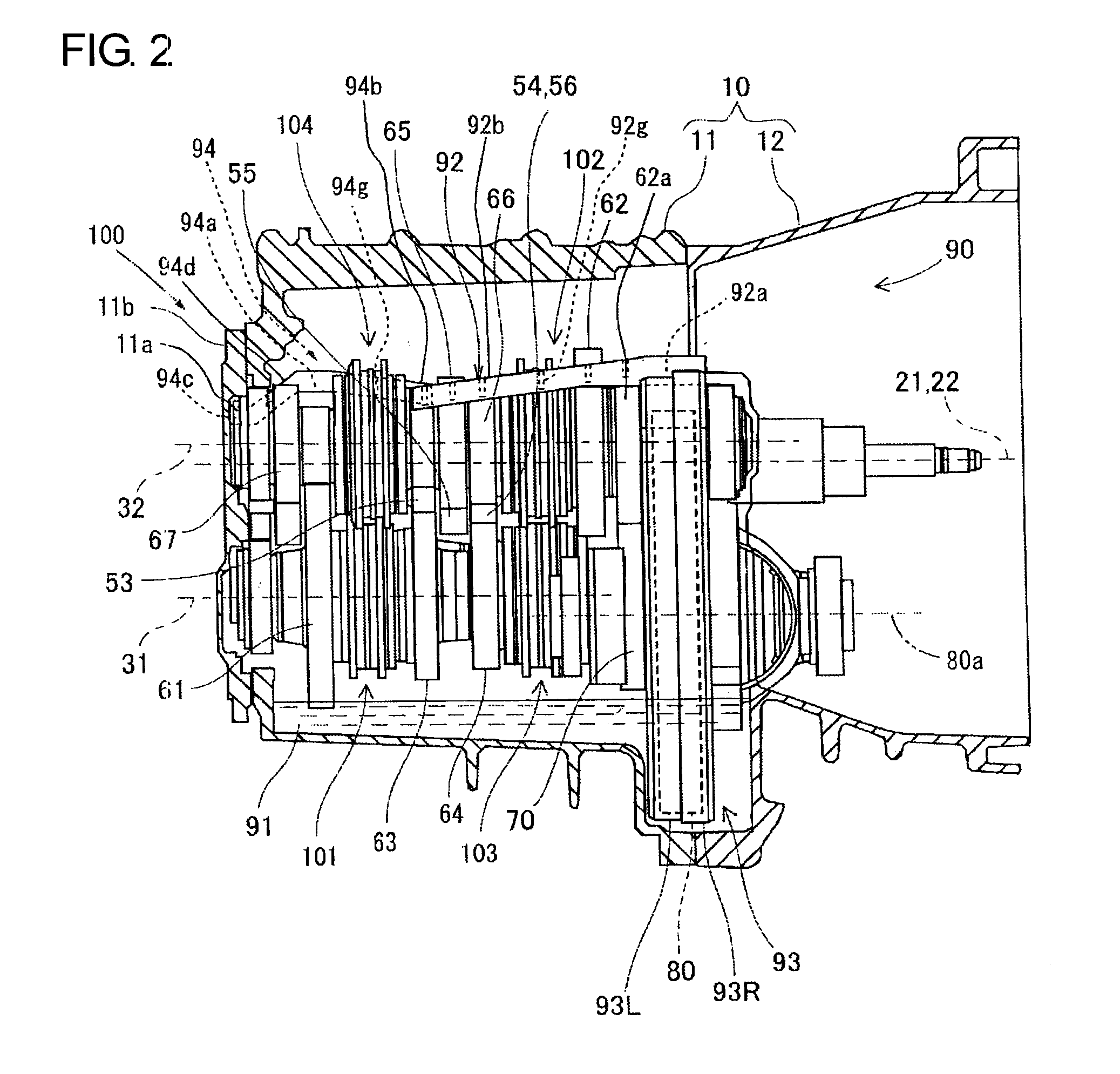
[0017]Hereafter, a transmission 1 for a vehicle in a first embodiment to which the present invention is embodied will be described with reference to FIGS. 1 to 3. As shown in FIGS. 1 to 3, the transmission 1 is a dual-clutch automatic transmission with seven forward speeds and is provided with a first input shaft 21, a second input shaft 22, a first output shaft 31 and a second output shaft 32 as shaft members to extend in the axial direction in a case 10. Further, in the case 10, there are provided a dual clutch 40, drive gears 51-57 (corresponding to “drive gears” in the claimed invention) for respective speed change stages, final reduction drive gears 58, 68, driven gears 61-67 for the respective speed change stages, a reverse gear 70, a ring gear 80 (corresponding to the “first large-diameter gear” in the claimed invention), a first lubrication mechanism 90 and a second lubrication mechanism 100. The final reduction drive gears 58, 68, the driven gears 61-67 and the reverse gear...
second embodiment
[0058]Next, a second embodiment will be described with reference to FIGS. 4 and 5. The construction of a transmission 111 in the second embodiment mainly differs in that the transmission 111 is a manual transmission though the transmission 1 in the first embodiment is a dual-clutch automatic transmission. In this connection, gears or the like of the transmission 111 differ in construction or arrangement from those of the transmission 1. Other constructions are the same as those in the first embodiment, and therefore, detailed description of the other constructions is omitted for the sake of brevity. Further, the operation of the manual transmission 111 is well known in the art, of which description is also omitted for the sake of brevity. Hereinafter, the differences only will be described.
[0059]As shown in FIGS. 4 and 5, the transmission 111 being a manual transmission is provided in the mission case 11 with an input shaft 123 and an output shaft 133 each being as shaft member as w...
third embodiment
[0076]Next, a third embodiment will be described with reference to FIG. 6 being a skeletal figure. Like the transmission 1 in the foregoing first embodiment, a transmission 211 in the third embodiment is a dual-clutch automatic transmission and a six-forward speed transmission. In the transmission 1 in the first embodiment, the respective shaft members are constituted by the first and second output shafts 31, 32 which are arranged in parallel to the first and second input shafts 21, 22 arranged coaxially. On the contrary, the transmission 211 in the third embodiment constitutes respective shaft members by first and second input shafts 214, 215 which are arranged coaxially as is the case of the transmission 1, an output shaft 212 arranged in axial alignment with the input shafts 214, 215, and a counter shaft 213 arranged in parallel to the first and second input shafts 214, 215, and differs in this respect from those in the foregoing embodiments.
[0077]Another difference resides in th...
PUM
 Abstract
Description
Claims
Application Information
 - R&D
- Intellectual Property
- Life Sciences
- Materials
- Tech Scout
- Unparalleled Data Quality
- Higher Quality Content
- 60% Fewer Hallucinations
Browse by: Latest US Patents, China's latest patents, Technical Efficacy Thesaurus, Application Domain, Technology Topic, Popular Technical Reports.
© 2025 PatSnap. All rights reserved.Legal|Privacy policy|Modern Slavery Act Transparency Statement|Sitemap|About US| Contact US: help@patsnap.com