Hose bend bleeder for ammonia application system

Inactive Publication Date: 2010-12-23
WARD DAVID P
View PDF8 Cites 8 Cited by
  • Summary
  • Abstract
  • Description
  • Claims
  • Application Information

AI Technical Summary

Problems solved by technology

At times, however, a relatively small amount of liquid ammonia will remain at the bottom of a bend in the hose due to gravity.
Due to the extremely hazardous nature of ammonia, however, the relatively small amount of hose bend bleed off liquid must be directed away from the face of the technician doing the bleed off.

Method used


Image

  • Hose bend bleeder for ammonia application system
  • Hose bend bleeder for ammonia application system
  • Hose bend bleeder for ammonia application system

Examples


Embodiment Construction

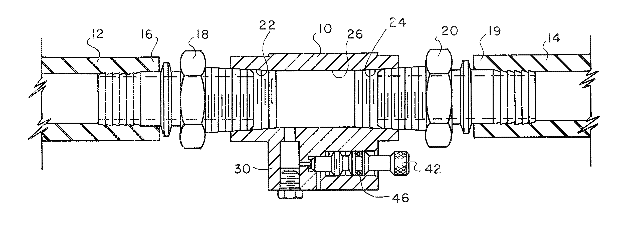
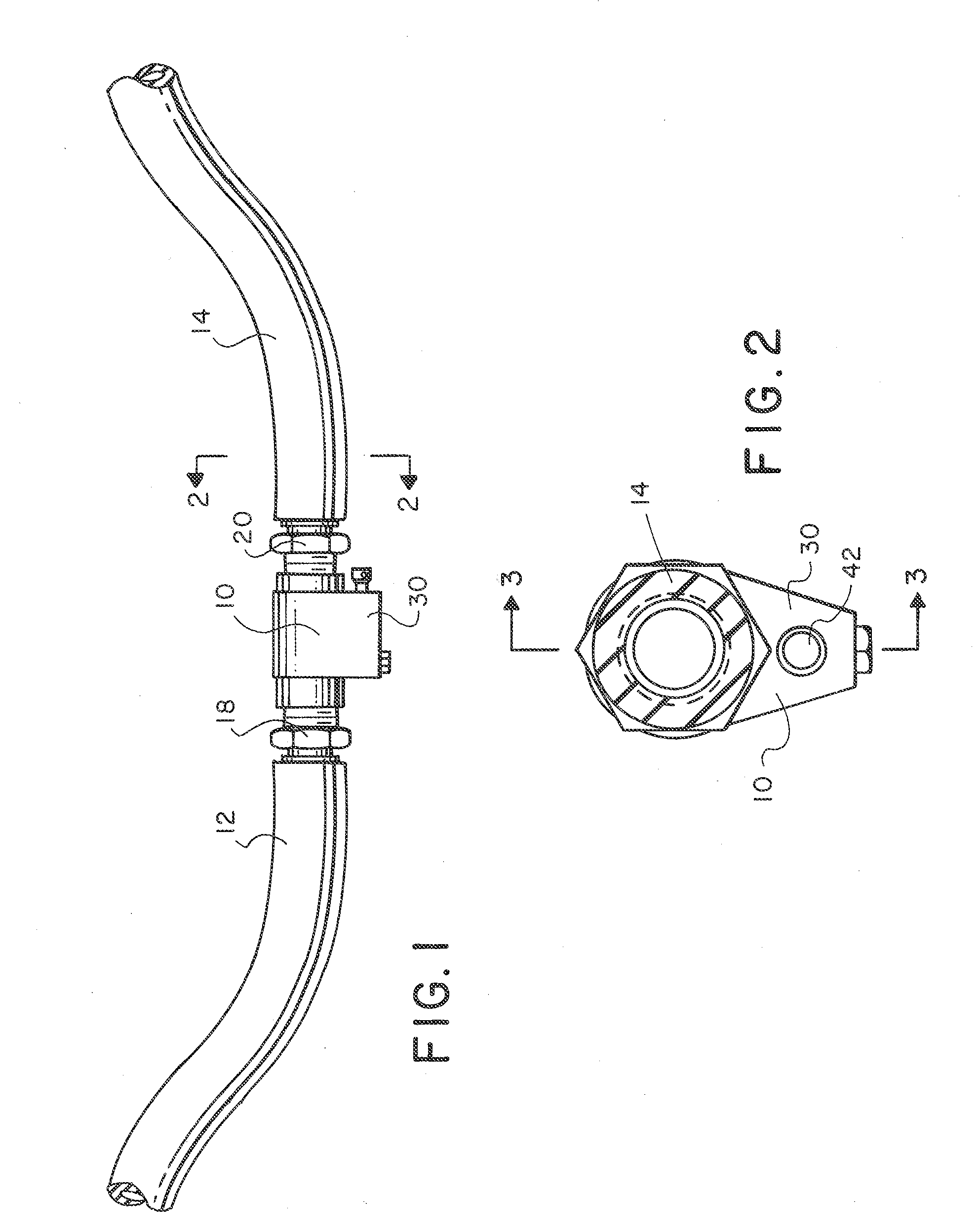
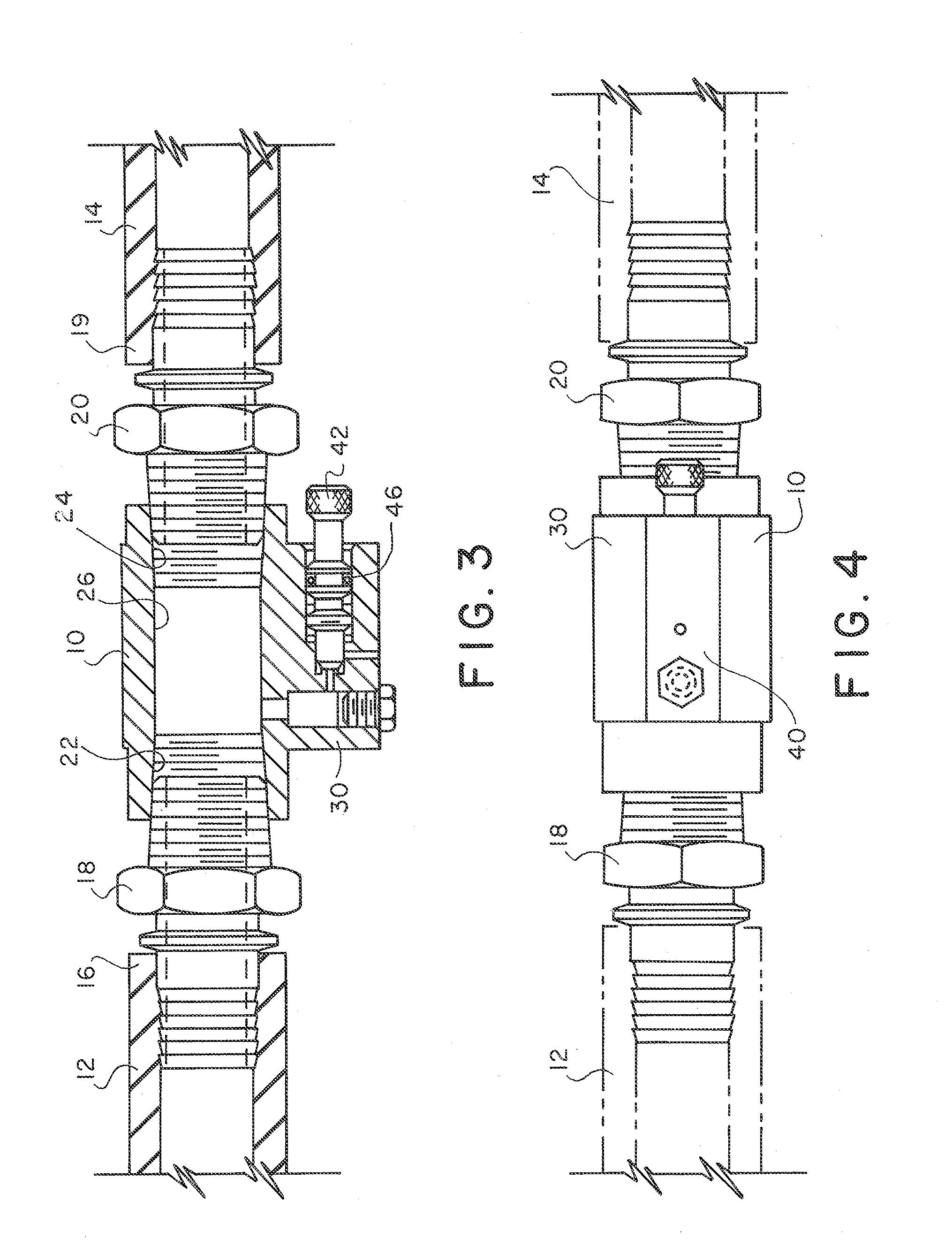
[0011]Referring to FIGS. 1-5, where like numerals refer to like and corresponding parts, a hose bend bleeder 10 is combined with first and second hoses 12 and 14. First hose 12 has an end 16 connected to a first hose fitting 18. First hose fitting 18 is at the same vertical elevation as end 16 and lower than the remainder of first hose 12. Second hose 14 has an end 19 connected to a second hose fitting 20. Second hose fitting 20 is at the same vertical elevation as end 19 and lower than the remainder of second hose 14. Ends 16,19 and hose fittings 18,20 are all at the same elevation.

[0012]The hose bend bleeder 10 has first and second openings 22,24 connected to the first and second hose fittings 18,20, respectively, such that the hose bend bleeder 10 is located at the bottom of a bend in the flow path established by the hoses 12,14.

[0013]The hose bend bleeder 10 includes a main passageway 26 between the first and second openings 22,24. The main passageway 26 is collinear with the fi...


PUM


Abstract

A hose bend bleeder is combined with first and second hoses, with the hose bend bleeder being located at the bottom of a bend in a flow path established by the hoses. The hose bend bleeder has a bleed screw and a downwardly facing exit passageway.

Description

BACKGROUND OF THE INVENTION[0001]This invention relates to pressurized systems used in the transfer of product, through hoses, to pressure vessels. More particularly, the invention relates to equipment used in the transfer of agricultural ammonia from storage tanks and wagon-mounted nurse tanks, and provides a safety device for bleeding off undesired liquid ammonia at the bottom of a hose bend.[0002]Liquid anhydrous ammonia (NH,) has long been used as a fertilizer for corn, grains and other crops. The typical ammonia application system consists of a nurse tank trailed behind a tool bar which is attached to a tractor. Application rate is controlled by a meter. The nurse tank is a trailer-mounted pressure vessel which contains the ammonia in its liquid state. The ammonia flows through a hose from the tank to the meter, then through more hose to one or more dividing manifolds, and finally through suitable hoses to the applicator knives which inject the ammonia into the soil. Hoses are ...

Claims


Application Information

Patent Timeline
IPC IPC(8): F15B20/00
CPCF16L55/07F16K24/04Y10T137/87901Y10T137/87169Y10T137/877
Inventor WARD, DAVID P.
Owner WARD DAVID P
Why Eureka
Try Eureka