Clutch system exhaust auxiliary device and method

A technology of an auxiliary device and an exhaust pipe, which is applied in the field of automobile clutch system, can solve the problems of hazards to personnel, difficulty in shifting gears, and reduction of maintenance efficiency, so as to improve production safety, facilitate exhaust and oil discharge, and save human resources. Effect

Active Publication Date: 2019-06-04
ANHUI JIANGHUAI AUTOMOBILE GRP CORP LTD
View PDF6 Cites 0 Cited by
  • Summary
  • Abstract
  • Description
  • Claims
  • Application Information

AI Technical Summary

Problems solved by technology

[0004] 1. Usually the total time-consuming is about 10-30min, which takes a long time and requires 2 people to coordinate the operation, which reduces the maintenance efficiency and causes a lot of labor costs;
[0005] 2. The exhaust and oil discharge of the clutch system is not complete and not standardized, resulting in incomplete separation of the clutch and difficulty in shifting gears. After a period of time, it will also cause air leakage in the pipeline system, insufficient oil pressure in the pipeline, and failure of the clutch system. etc., affecting the driving of the vehicle
[0006] 3. During the above-mentioned manual exhaust and oil discharge, the oil (brake fluid DOT4, corrosive) injected from the oil pressure filling port 04 is likely to be sprayed out from the air release port and sprayed to the exposed skin area of ​​the operator, which is harmful to personnel , while the residual oil flows to the ground, causing pollution and waste
[0007] 4. The assembly line uses vacuum equipment for refilling. This equipment is expensive and only suitable for use in the assembly line. It is not suitable for vehicle repair, maintenance, trial production and other workshops. There are certain limitations in vehicle exhaust and oil discharge.

Method used


Image

  • Clutch system exhaust auxiliary device and method
  • Clutch system exhaust auxiliary device and method
  • Clutch system exhaust auxiliary device and method

Examples


Embodiment Construction

[0054] The embodiments described below by referring to the figures are exemplary only for explaining the present invention and should not be construed as limiting the present invention.

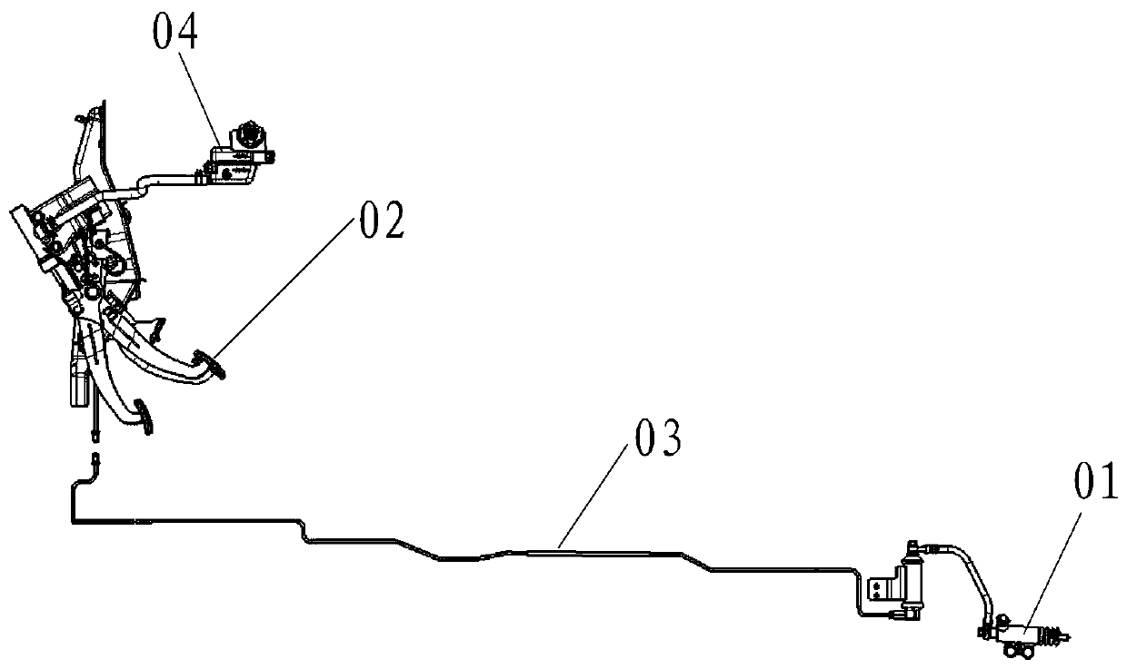
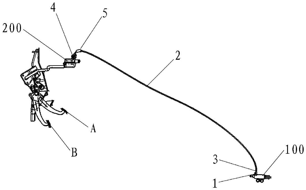
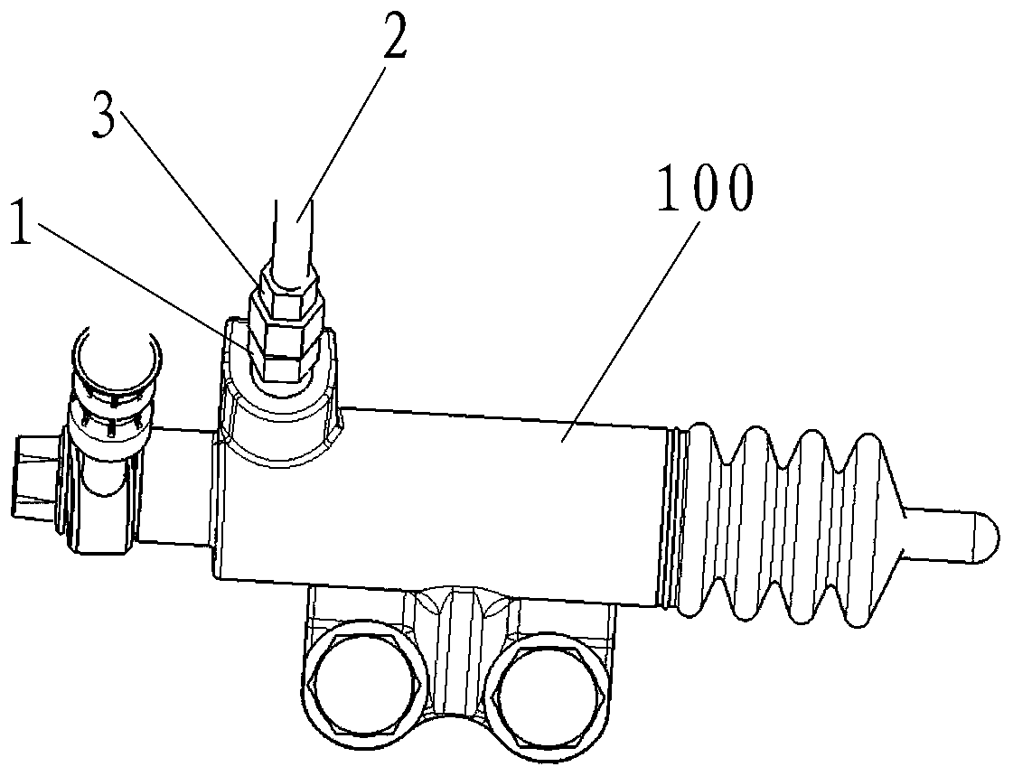
[0055] Embodiments of the present invention: as Figure 2-4 As shown, a clutch system exhaust auxiliary device is used for the exhaust and oil discharge operation of the clutch pipeline. Its components are sealed and connected, including the clutch cylinder 100. Air release screw 1, also includes exhaust Pipe 2, the exhaust pipe 2 is connected to the sub-cylinder air release screw 1 through the exhaust pipe oil inlet joint 3, the exhaust pipe 2 is connected to the brake oil pot 200 through the exhaust pipe oil discharge joint 4, the The exhaust pipe 2 is provided with an exhaust observation port 5 near the position of the exhaust pipe oil discharge joint 4. Specifically, the exhaust pipe 2 and the exhaust observation port 5 can be ordinary circular transparent polyethylene rubber pipes. Fixe...


PUM


Abstract

The invention discloses a clutch system exhaust assisting device. The clutch system exhaust assisting device comprises a wheel cylinder bleed screw on a clutch wheel cylinder and further comprises anexhaust pipe. The exhaust pipe is connected with the wheel cylinder bleed screw through an exhaust pipe oil inlet connector. The exhaust pipe is connected with a braking oil pot through an exhaust pipe oil discharging connector. The position, close to the exhaust pipe oil discharging connector, of the exhaust pipe is provided with an exhaust observation port. The wheel cylinder bleed screw, the exhaust pipe oil inlet connector, the exhaust pipe and the exhaust pipe oil discharging connector are in communication through an oil path. An oil path control structure is further included and comprises an oil inlet control structure and an oil discharging control structure, the oil inlet control structure is arranged on the exhaust pipe oil inlet connector, and the oil discharging control structure is arranged on the exhaust pipe oil discharging connector. The invention further provides an exhaust method adopting the above device. By application of the provided device and method, one person can conduct control, the human resource is saved, and time is saved; and the situation that oil liquid is sprayed to the naked skin of the human body can be avoided, and production safety is improved.

Description

technical field [0001] The invention relates to the field of automobile clutch systems, in particular to a clutch system exhaust auxiliary device and an exhaust method using the device. Background technique [0002] The clutch system is an indispensable part of the manual transmission car. During the driving process, the driver manipulates the clutch pedal, and through the transmission of the hydraulic pipeline, the separation and combination of the clutch can be effectively realized, and then the power transmission can be completed to realize the normal driving function of the car. . In order to ensure the above functions, it is necessary to ensure that the hydraulic pressure in the clutch pipeline effectively transmits the movement from the pedal, which requires that the hydraulic pressure in the pipeline must not contain gas. Exhaust and oil discharge operation. [0003] Existing clutch system exhaust structure such as figure 1 As shown, it includes the sub-cylinder ex...

Claims


Application Information

Patent Timeline
Patent Type & Authority Patents(China)
IPC IPC(8): F16D25/12
CPCF16D25/12
Inventor 杨允辉郭静葛士显袁杰佟维幸振帆宋康黄从奎岳丽姣陆静静
Owner ANHUI JIANGHUAI AUTOMOBILE GRP CORP LTD
Why Eureka
Try Eureka