Air bleed mechanism for a submersible turbine pump

a submersible turbine and air bleed technology, which is applied in the direction of piston pumps, liquid handling, packaging goods types, etc., can solve the problem that air will end up trapped in the fuel, and achieve the effect of easy flow

Active Publication Date: 2005-09-29
VEEDER ROOT
View PDF22 Cites 1 Cited by
  • Summary
  • Abstract
  • Description
  • Claims
  • Application Information

AI Technical Summary

Benefits of technology

[0006] The air bleed mechanism includes an air bleed screw inserted into a threaded orifice in the manifold. The threaded orifice is coupled to both the bypass tube and the fuel discharge chamber. When the air bleed screw is rotated downward, the bypass tube is fluidly decoupled from the fuel discharge chamber. When the air bleed screw is rotated upward, the bypass tube is fluidly coupled to the fuel discharge chamber. In this manner, a technician can control the removal of air via the air bleed screw.
[0007] The air bleed screw includes a head portion and a shaft portion. The head portion allows the air bleed screw to be manually rotated by a technician having a screw driver. The shaft portion includes a sealing portion and a threaded portion. The sealing portion prevents fuel and / or vapors from leaking into the environment. The sealing portion further seals the fuel discharge chamber from the bypass tube when the air bleed screw is rotated downward.
[0008] In one embodiment, the threaded portion of the air bleed screw includes at least one flat, vertical side that creates an air flow passage between threaded portion of the air bleed screw and the threaded orifice into which the screw is inserted. The air flow passage created by the at least one flat, vertical side allows air to easily flow from the fuel discharge chamber to the bypass tube when the air bleed screw is rotated upward.
[0009] The air bleed screw may also include a pin passing through an orifice in the shaft portion at a location that is within the fuel discharge chamber. The pin prevents the air bleed screw from being completely removed from the manifold, thereby preventing misplacement of the screw and leakage of fuel, air, and / or vapors into the environment.

Problems solved by technology

If the air is not removed from the manifold, the air will ultimately be trapped in the fuel piping network and dispensed during the sale of fuel.
Further, the air trapped in the manifold negatively influences both mechanical and electrical leak detection systems, and therefore must be removed for these systems to operate properly.

Method used


Image

  • Air bleed mechanism for a submersible turbine pump
  • Air bleed mechanism for a submersible turbine pump
  • Air bleed mechanism for a submersible turbine pump

Examples


Embodiment Construction

[0017] The embodiments set forth below represent the necessary information to enable those skilled in the art to practice the invention and illustrate the best mode of practicing the invention. Upon reading the following description in light of the accompanying drawing figures, those skilled in the art will understand the concepts of the invention and will recognize applications of these concepts not particularly addressed herein. It should be understood that these concepts and applications fall within the scope of the disclosure and the accompanying claims.

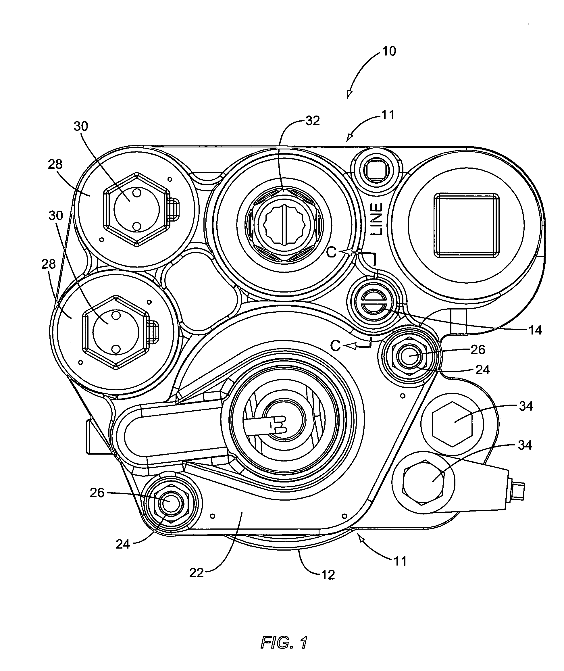
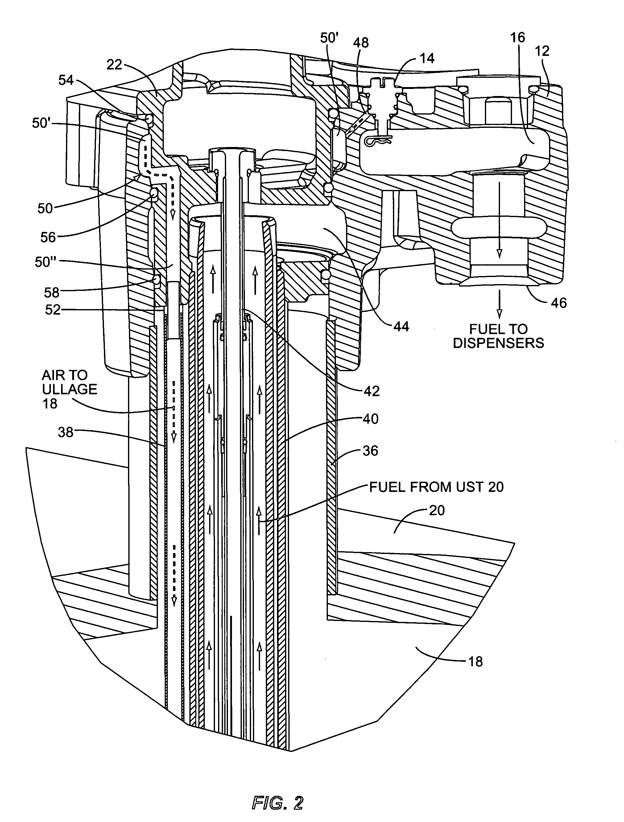
[0018] As illustrated in FIG. 1, the submersible turbine pump (STP) 10 of the present invention provides a casing 11 and includes a manifold 12. According to the present invention the manifold 12 includes an air bleed mechanism 14 that when activated bleeds air from a fuel discharge chamber 16 (FIG. 2) into an ullage area 18 (FIG. 2) of an underground storage tank 20 (FIG. 2). When the air bleed mechanism is deactivated the fuel...


PUM

PropertyMeasurementUnit
pressureaaaaaaaaaa
dimensionsaaaaaaaaaa
areaaaaaaaaaaa

Abstract

A manifold for a submersible turbine pump having an air bleed mechanism for removing air from a discharge chamber of the manifold. The manifold includes the discharge chamber that receives fuel pumped from an underground storage tank (UST), the air bleed mechanism, an air return path coupled to the UST, and a bypass tube coupled to the air return path. When the air bleed mechanism is activated, the fuel discharge chamber is fluidly coupled to the bypass tube, thereby allowing air from the fuel discharge chamber to flow to the ullage of the UST. In one embodiment, the air bleed mechanism is an air bleed screw inserted into a threaded orifice in the manifold. The threaded orifice is coupled to both the bypass tube and the fuel discharge chamber. When the air bleed screw is rotated upward, the bypass tube is coupled to the fuel discharge chamber.

Description

FIELD OF THE INVENTION [0001] The present invention relates to a manifold for a submersible turbine pump, and more particularly relates to a manifold including an air bleed mechanism for removing air from a discharge chamber of the manifold and returning the air to an underground storage tank. BACKGROUND OF THE INVENTION [0002] Submersible turbine pumps (STPs) are used at fuel dispensing sites to pump fuel from an underground storage tank (UST) to a plurality of fuel dispensers. The STP contains a turbine pump that draws fuel out of the UST. The STP includes a manifold that receives fuel from the UST through a riser pipe and that transfers the fuel to the fuel dispensers via a fuel piping network. When servicing of the STP is required, the STP is decoupled from the piping network and a top, or “packer,” is removed from the manifold of the STP. After the STP has been serviced, the packer is placed back on the manifold and the STP is re-coupled to the fuel dispensers. Accordingly, air...

Claims


Application Information

Patent Timeline
Patent Type & Authority Applications(United States)
IPC IPC(8): B67D7/68F16K24/04
CPCB67D7/68
Inventor DOLSON, RICHARD
Owner VEEDER ROOT
Why Eureka
Try Eureka