Startup source inverter

a technology of inverter and start-up source, which is applied in the direction of d ac network circuit arrangement, electrical apparatus, etc., can solve the problems of control device being unable to provide control and control device being destroyed

Inactive Publication Date: 2010-12-23
ADENSIS
View PDF6 Cites 16 Cited by
  • Summary
  • Abstract
  • Description
  • Claims
  • Application Information

AI Technical Summary

Benefits of technology

The technical effect of this patent is to provide a method to connect a photovoltaic system without causing damaging current spikes while also maintaining optimal performance under varying load demands. By quickly reducing the output voltage of the solar system and disconnecting it from its previous circuit configuration, the new system can adapt more easily to changes in demand on the electricity network.

Problems solved by technology

The technical problem addressed in this patent is how to connect an inverter to a power grid while preventing damage to the photovoltaic generators due to excessive voltages during abnormal conditions such as short circuits. Current methods require the inverters to have a limited operational range to avoid damaging the equipment, but this limits their efficiency. There is a need for an improved solution that allows for increased flexibility and reliability in connection to the power grid without sacrificing safety measures.

Method used


Image

  • Startup source inverter
  • Startup source inverter
  • Startup source inverter

Examples


Embodiment Construction

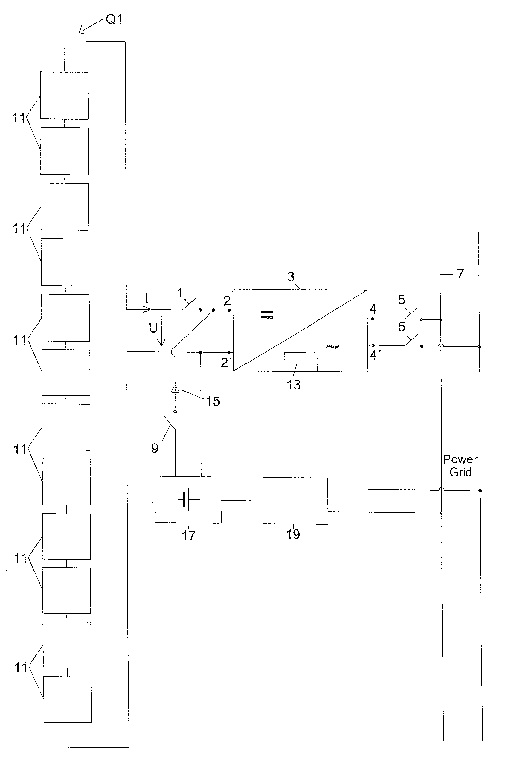
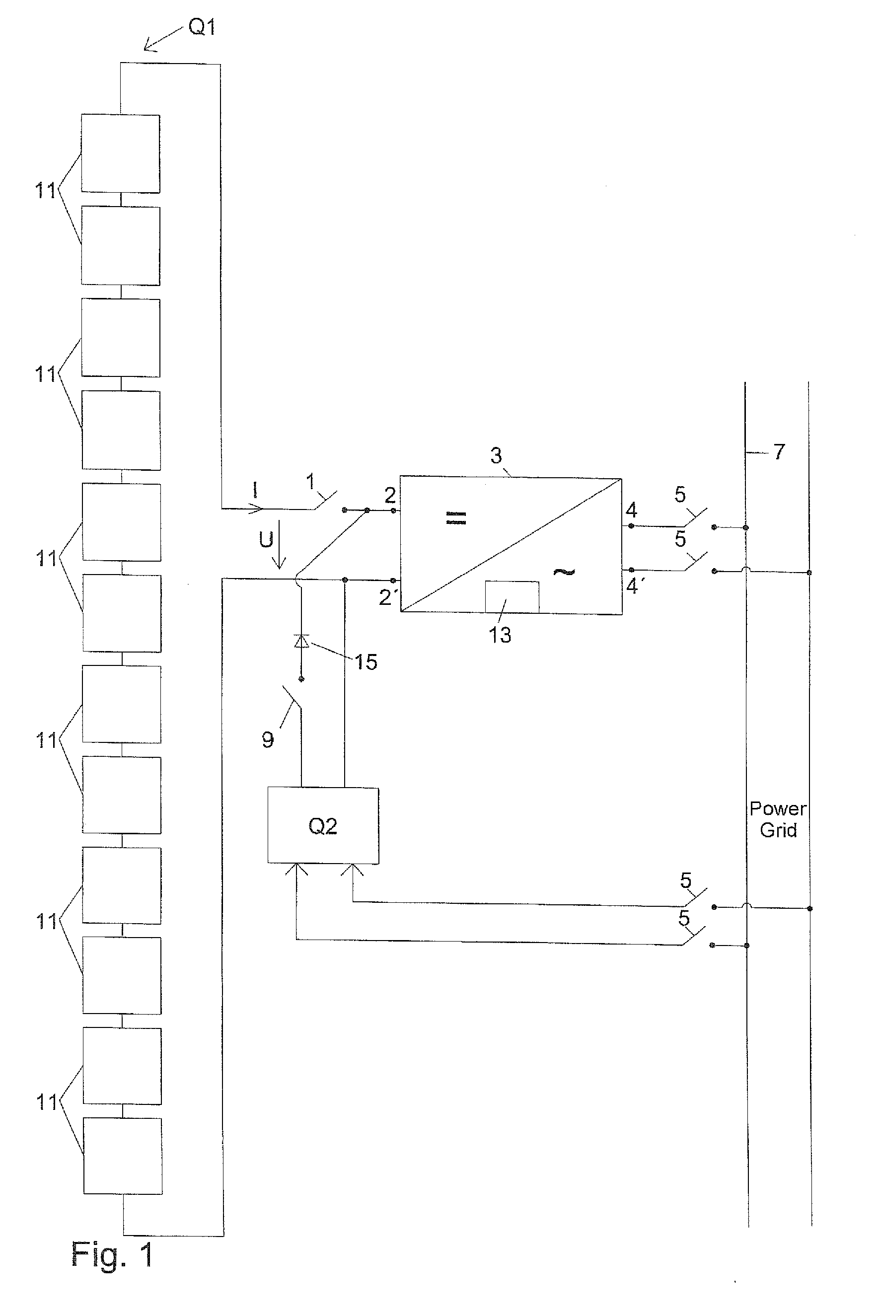
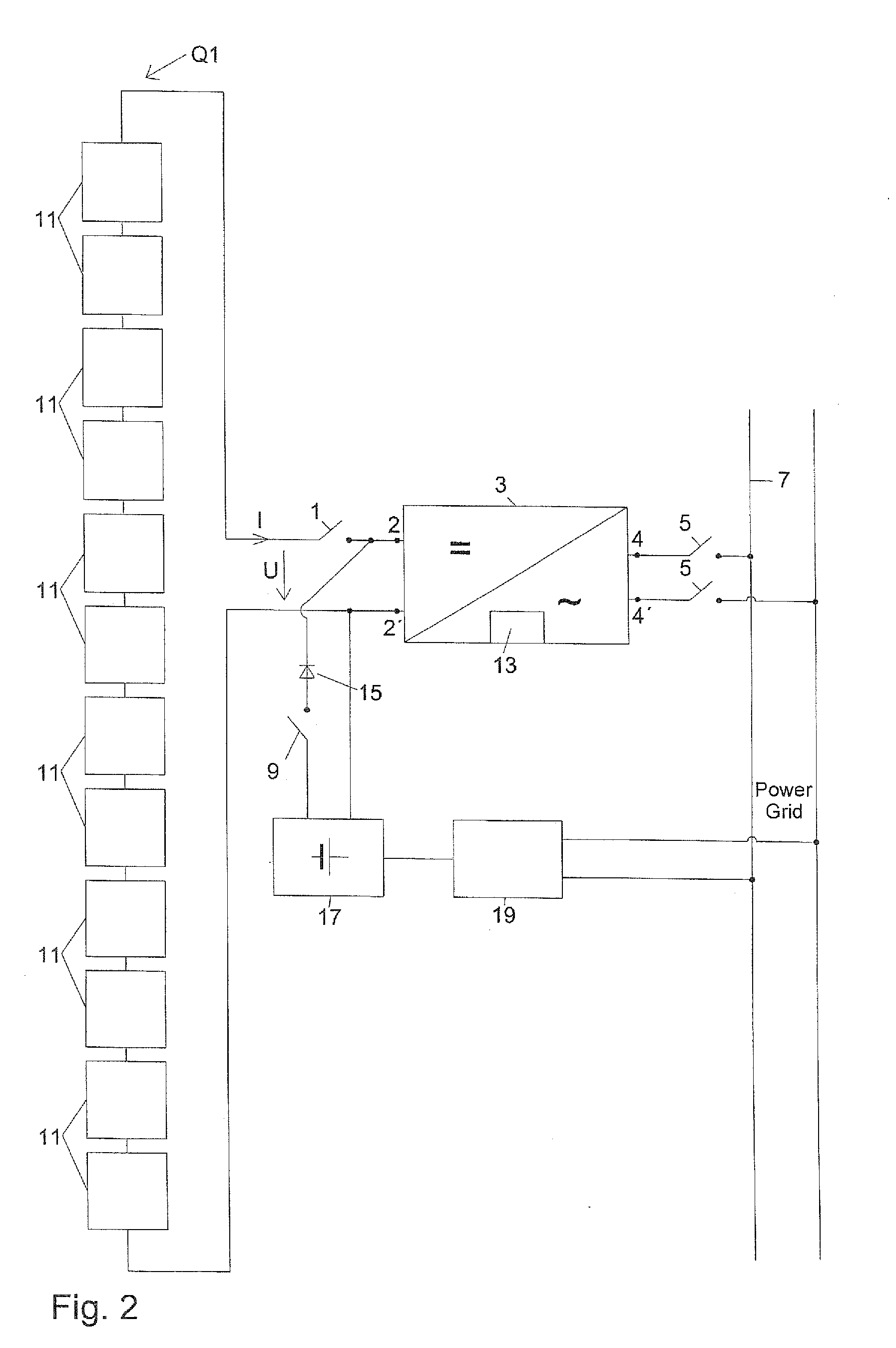
[0026]Throughout all the figures, same or corresponding elements may generally be indicated by same reference numerals. These depicted embodiments are to be understood as illustrative of the invention and not as limiting in any way. It should also be understood that the figures are not necessarily to scale and that the embodiments are sometimes illustrated by graphic symbols, phantom lines, diagrammatic representations and fragmentary views. In certain instances, details which are not necessary for an understanding of the present invention or which render other details difficult to perceive may have been omitted.

[0027]Turning now to the drawing, and in particular to FIG. 1, there is shown schematically a photovoltaic generator as a first energy source or primary energy source Q1. The photovoltaic generator Q1 is connected to the input terminals 2, 2′ of an inverter 3 via a first switch 1. The output contacts 4, 4′ of the inverter 3 can be connected via a switching element 5 to a pub...


PUM


Abstract

A method and an apparatus for setting up synchronization, with a power grid, of an inverter having a photovoltaic generator as a primary energy source is disclosed. The inverter is supplied with the energy from an additional energy source connected in parallel with input terminals of the inverter, wherein the additional energy source is a DC energy source operated independent from the primary energy source. The frequency, phase relationship and output voltage of the inverter supplied from the additional DC energy source are matched to the frequency, phase relationship and output voltage of the power grid, whereafter the primary energy source is connected to the inverter. With this method, an inverter dimensioned for a permissible open-circuit voltage can also be used under operating conditions, without requiring modifications of the circuitry of the primary energy source.

Description


Claims


Application Information

Patent Timeline
Owner ADENSIS
Why Eureka
Try Eureka