Battery pack

a battery pack and battery module technology, applied in secondary cell servicing/maintenance, cell components, electrochemical generators, etc., can solve the problems of battery module damage, battery module damage, battery module damage, etc., and achieve the effect of damaging the battery module and the battery modul

Inactive Publication Date: 2010-12-23
MAKITA CORP
View PDF20 Cites 87 Cited by
  • Summary
  • Abstract
  • Description
  • Claims
  • Application Information

AI Technical Summary

Benefits of technology

[0022]The battery pack according to the present teachings can detect the replacement of the battery module (i.e., battery cells) by the user, and can automatically perform the necessary processes. Accordingly, the damage to the battery modules and battery pack when the battery module (i.e., some of the battery cells) is replaced by the user can be prevented.

Problems solved by technology

When a battery pack is used repeatedly, battery cells inside the battery pack degrade.
Instead, only some of the battery cells seriously degrade.
In other words, even though only some of the battery cells have degraded, the battery pack is no longer able to function at a sufficient level.
However, as noted below, it is not easy for a user to replace degraded battery cells.
When a battery cell is replaced in a state in which a high voltage has been generated, the battery pack may be damaged due to an electrical short circuit.
However, even if circuit breakers are provided, the battery pack may be damaged in an event that the user forgets to open the circuit breakers and replaces the battery cells.
However, even if this check function is provided in the battery pack, the user may forget to use the check function, and thus still useable battery cells may be replaced in error.
Third, after replacing the battery cells, the user may need to perform a balance process in order to equalize the charge states of all battery cells.
In addition, when the charge states of the plurality of battery cells are equalized, the performance (e.g., a charge capacity) of the entire battery pack dramatically declines, and some of the battery cells degrade quickly.
However, even if this type of function is provided, the user may forget to use the function, and then reuse the battery pack with the battery cells in an unequalized state.
In addition, if these processes and operations are not performed, problems such as a damage to the battery pack and an early degradation of the battery cells may arise, as well as a significantly shortened battery pack life.

Method used


Image

  • Battery pack
  • Battery pack
  • Battery pack

Examples


embodiment 1

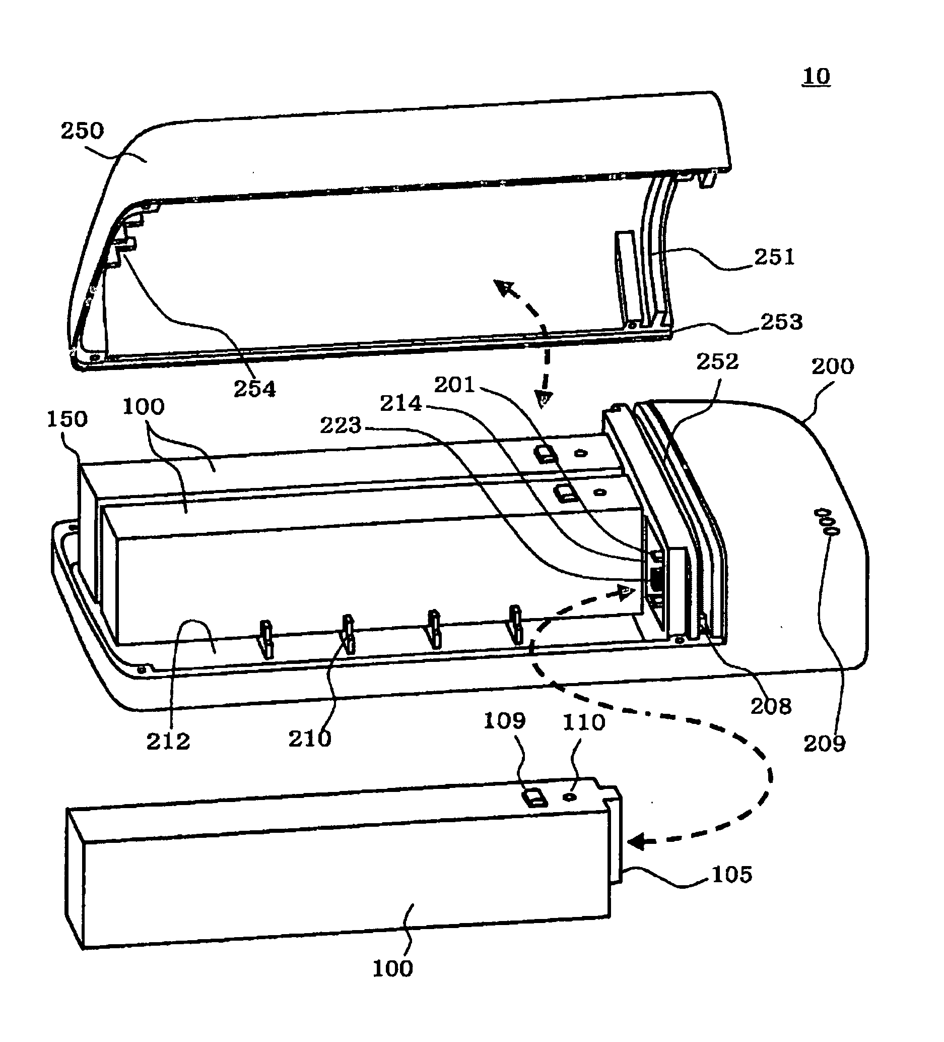
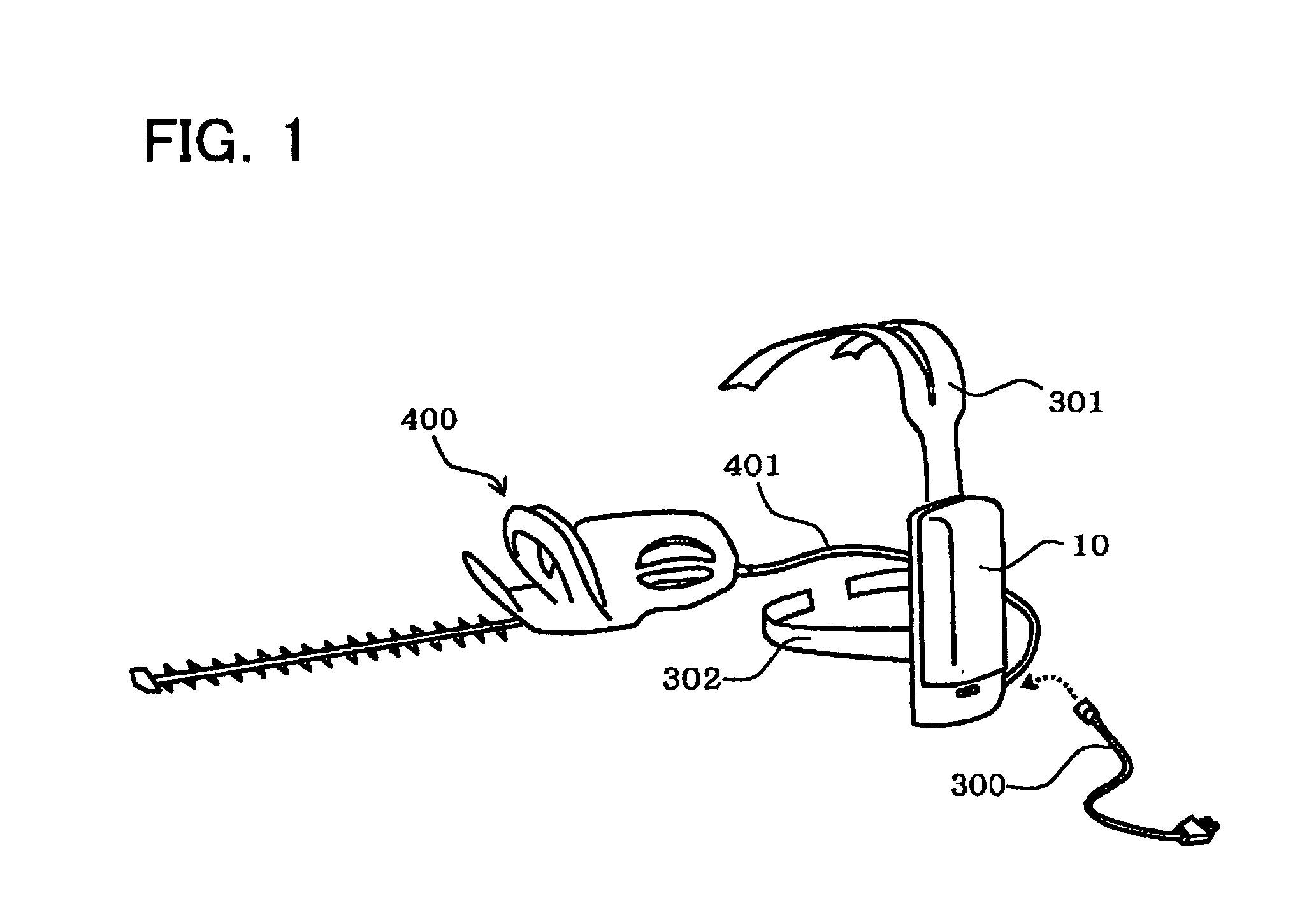
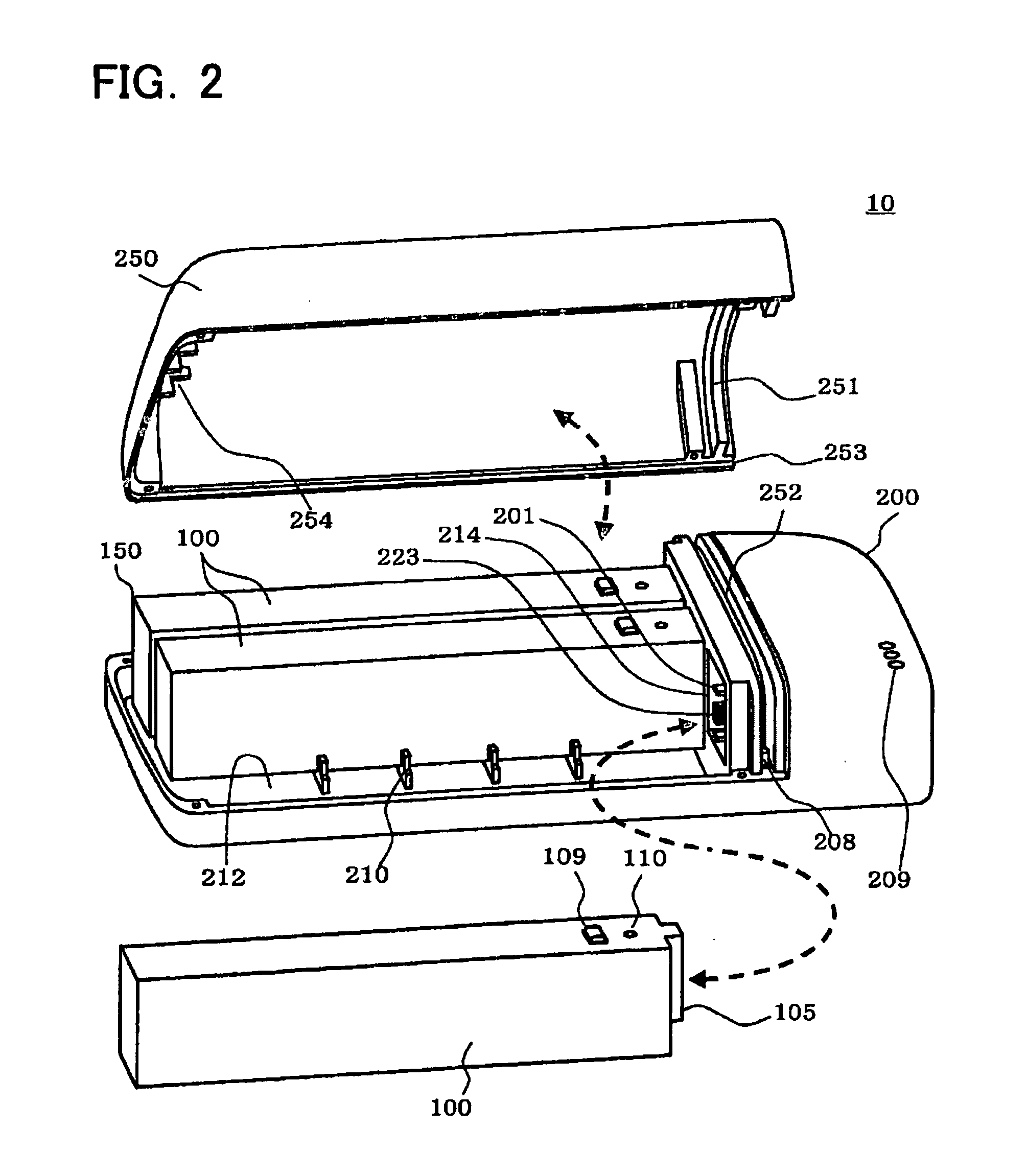
[0054]A battery pack 10 of Embodiment 1 will be described with reference to the drawings. As shown in FIG. 1, the battery pack 10 is connected to an electric power tool 400 by a power supply cord 401, and supplies electric power to the electric power 400 as being a power source therefor. The power supply cord 401 is removable from the battery pack 10. When using the electric power tool 400, the electric power cord supply 301 is installed onto the battery pack 10, and when the electric power tool is not used, the power supply cord 401 is removed from the battery pack 10. As described below, the battery pack 10 is comprised of 30 battery cells connected in series, and has a nominal voltage of 108 volts.

[0055]Note that in FIG. 1, an electric hedge trimmer is illustrated as an example of the electric power tool 400, but the electric power tool 400 to which electric power is supplied by the battery pack 10 is not limited to a hedge trimmer. The battery pack 10 can be used as a power sour...

embodiment 3

[0186]A battery pack 30 of Embodiment 3 will be described. FIG. 15 shows an outline of the structure of the battery pack 30 of Embodiment 3. As with the battery pack 10 of Embodiment 1, the battery pack 30 is capable of being recharged, and can supply that electric power to the electric power tool 400 (omitted in FIG. 15). The battery pack 30 of Embodiment 3 has the same construction as the battery pack 10 of Embodiment 1. In addition, the same reference numbers are associated with the same structural elements found in Embodiment 1.

[0187]As shown in FIG. 15, the battery pack 30 comprises three battery modules 100, and a pack main body 200. Each battery module 100 is equipped with battery cells 101 that are connected in series (omitted in FIG. 15). The plurality of battery modules is removable from the pack main body 200, and the pack main body 200 connects the plurality of installed battery modules 100 in series. In addition, the pack main body 200 can supply electric power from the...


PUM

PropertyMeasurementUnit
voltageaaaaaaaaaa
voltageaaaaaaaaaa
nominal voltageaaaaaaaaaa

Abstract

A battery pack is provided with a plurality of battery modules; a pack main body that removably receives the plurality of battery modules; a movable member that prohibits the plurality of battery modules from being attached to and removed from the pack main body at a first position; at least one sensor that detects whether the movable member is located at the first position or not; and a controller that performs at least one predetermined processing based on detection by the at least one sensor.

Description

CROSS-REFERENCE TO A RELATED APPLICATION[0001]This application claims priority to Japanese Patent Application No. 2009-204578 filed on Sep. 4, 2010, the contents of which are hereby incorporated by reference into the present application.TECHNICAL FIELD[0002]The present invention relates to a battery pack which supplies electric power to an electric device, and in particular relates to a battery pack used by an electric power tool. An “electric power tool” means any type of electric power tools including, but not limited to, electric drills, electric screw drivers, electric grinders, electric circular saws, electric chain saws, electric reciprocating saws, electric hedge trimmer, electric lawn mowers, electric brush cutters and electric blowers.DESCRIPTION OF RELATED ART[0003]A battery pack in which a plurality of battery modules is connected in series is disclosed in Japanese Application Publication No. 2008-159590. The battery pack has ten battery modules that are connected in seri...

Claims


Application Information

Patent Timeline
Patent Type & Authority Applications(United States)
IPC IPC(8): H02J7/00H01M10/48H01M50/213H01M50/244H01M50/247H01M50/271H01M50/569H02J7/02
CPCH01M2/1022H01M10/482H01M10/425H01M2/105Y02E60/10H01M50/213H01M50/247H01M50/569H01M50/271H01M50/244
Inventor SAKAKIBARA, KAZUYUKIMURATA, HIROSHIMATSUNAGA, YUTAKAGOTO, MUNETOSHI
Owner MAKITA CORP
Why Eureka
Try Eureka