Display device

a display device and display technology, applied in the field of display devices, can solve the problems of affecting the optical transfer function, the element will be “lost” for the display, and the optical switch will not perform the required optical switching

Active Publication Date: 2010-12-23
LIQUAVISTA BV
View PDF4 Cites 17 Cited by
  • Summary
  • Abstract
  • Description
  • Claims
  • Application Information

AI Technical Summary

Benefits of technology

[0008]It is an object of the invention to reveal the cause of the problems and to provide solutions for the problems. This results in a display device that is charac...

Problems solved by technology

Moreover, a pressure pulse exerted on the second support plate may create a shock wave, which propagates through the fluids and may even be magnified and which may cause a first fluid portion to flow over an element wall.
Already if an amount of less than 20%, for example 10% of the oil is removed from an electrowetting element, this element and its neighbour element that receives the expelled oil will no longer perform the required optical switching so that the optical transfer function is impaired.
If a larger amount of oil is expelled from an electrowetting element this element will be “lost” for the display.
In practice more than one pixel may get lost when pressure is exerted on the display.
In case of local pressure, for example by a finger or a pen-...

Method used


Image

  • Display device
  • Display device
  • Display device

Examples


Embodiment Construction

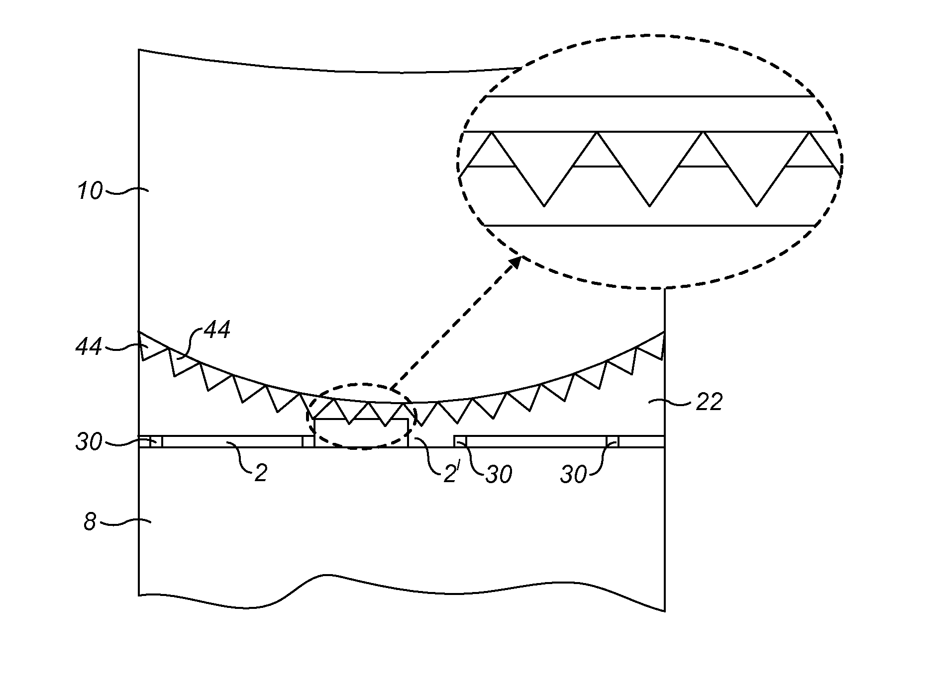
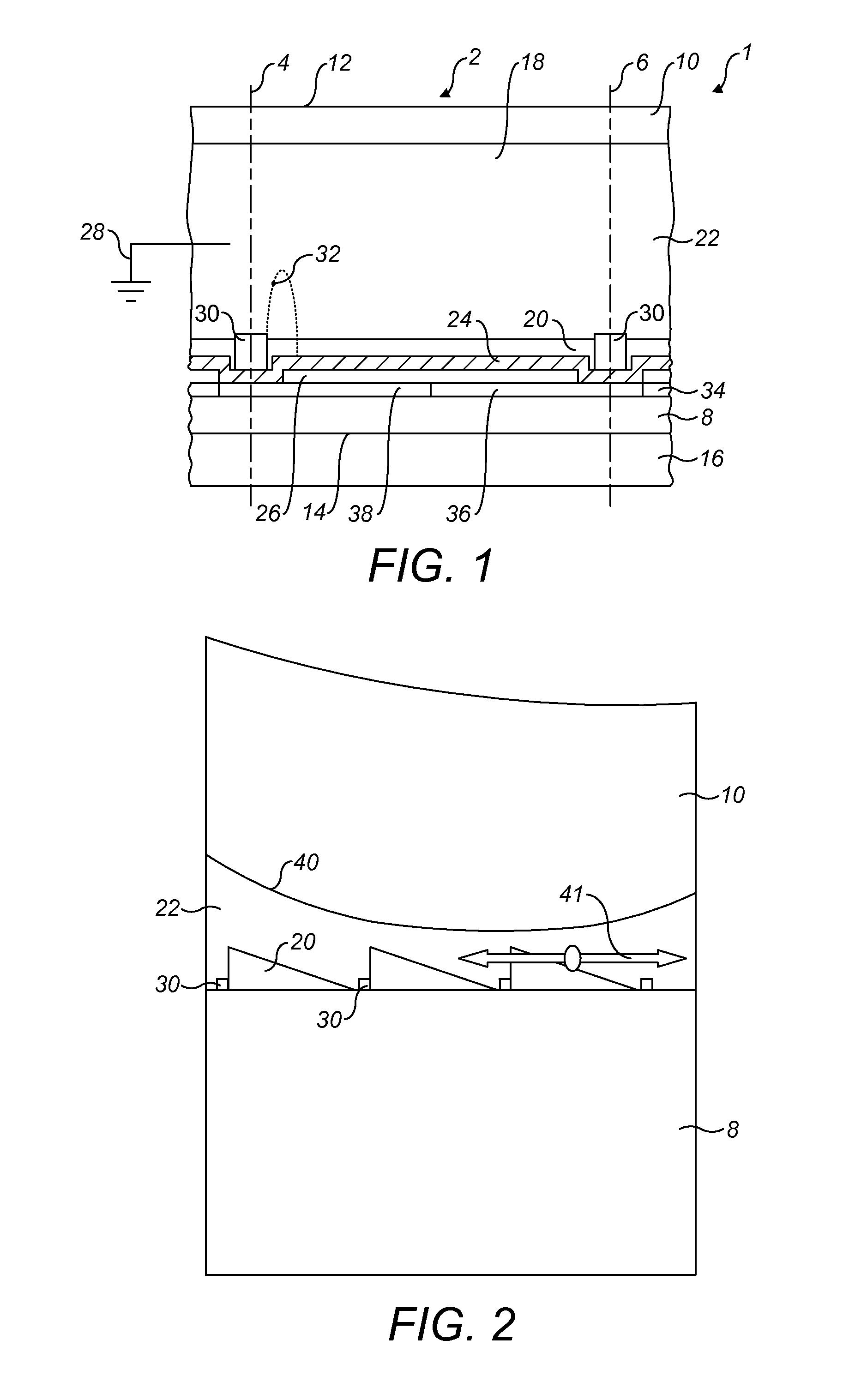
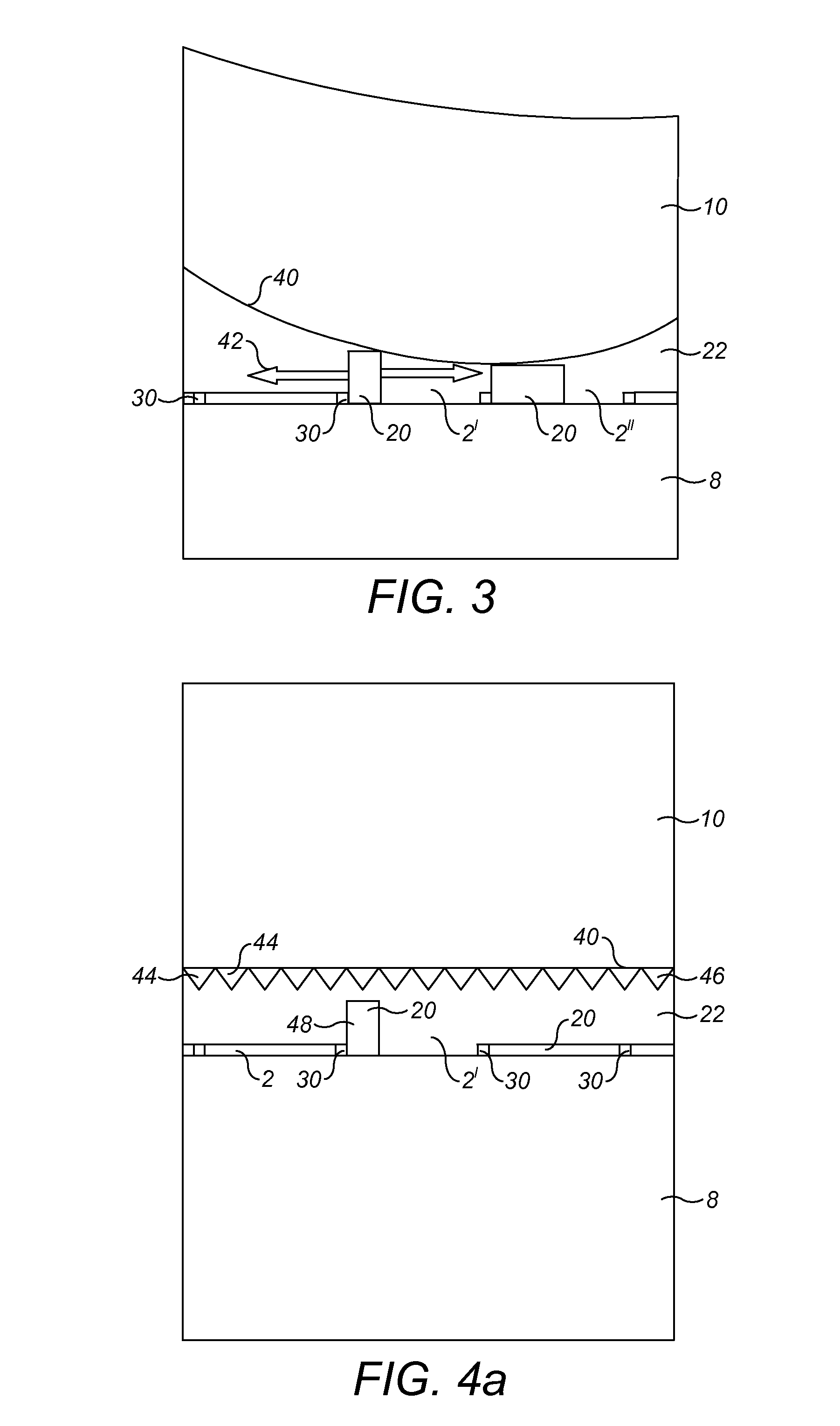
[0069]To illustrate the background of the invention the principle of an electrowetting display device will be described. FIG. 1 shows a diagrammatic cross-section of a part of an embodiment of such a device that has been described earlier. The display device 1 includes a plurality of electrowetting elements 2, only one of which is shown in the Figure. The lateral extent of this element is indicated in the Figure by two dashed lines 4, 6. The electrowetting elements comprise a first support plate 8 and a second support plate 10. The support plates may be separate parts of each electrowetting element, but the support plates are preferably in common for the plurality of electrowetting elements. The support plates may be made for instance of glass or polymer and may be rigid or flexible.

[0070]The display device has a viewing, or front-, side 12 on which an image formed by the display device can be seen and a rear, or back-, side 14. In some displays the viewing can also be done from sid...


PUM


Abstract

A display device comprising picture elements, which are constituted by electrowetting elements having at least one first fluid and a second fluid immiscible with each other within a space between a first support plate and a second support plate, the second fluid being electro-conductive or polar. The first fluid in each element is at the side of the first support plate confined by element walls, and the second fluid is shared by a plurality of picture elements, characterised by a preventer for preventing first fluid portions from being expelled from its confinement when forces other than electrowetting forces are exerted on this fluid.

Description

CROSS REFERENCE TO RELATED APPLICATIONS[0001]This Patent Application is a continuation-in-part of International Patent Application No. PCT / EP200 / 055084 filed on Apr. 27, 2009, entitled, “DISPLAY DEVICE” which claims priority to GB0807667.1 filed Apr. 28, 2008, the contents and teachings of which are hereby incorporated by reference in their entirety.FIELD OF THE INVENTION[0002]The invention relates to a display device comprising picture elements, which are constituted by electrowetting elements having at least one first fluid and a second fluid immiscible with each other within a space between a first support plate and a second support plate, the second fluid being electro-conductive or polar, whereby the first fluid in each element is at the side of the first support plate confined by element walls and the second fluid is shared by a plurality of picture elements.BACKGROUND OF THE INVENTION[0003]Such a display device, meanwhile known as an electrowetting display (EWD), may be used ...

Claims


Application Information

Patent Timeline
IPC IPC(8): G02B26/00B05D3/02B05D3/12
CPCG02B26/005
Inventor HAYES, ROBERT A.GIRALDO, ANDREASLACK, ANTHONY JOHNFEENSTRA, JOHANNES BOKKEVAN DIJK, ROYSCHRAM, IVAR
Owner LIQUAVISTA BV
Why Eureka
Try Eureka