Fuel cell simulator and fuel cell

a fuel cell and simulator technology, applied in the field of fuel cell simulators, can solve the problems of high cost of described elements forming fuel cells, and it is difficult to predict the power generation performance of fuel cells with high accuracy through simulation

Active Publication Date: 2010-12-23
TOYOTA JIDOSHA KK
View PDF6 Cites 19 Cited by
  • Summary
  • Abstract
  • Description
  • Claims
  • Application Information

AI Technical Summary

Benefits of technology

[0007]It is therefore an advantage of the present invention to provide a fuel cell simulator which is capable of predicting...

Problems solved by technology

Because the above-described elements forming a fuel cell are expensive, simulation technologies are being widely used for designing and manufacturing a fuel cell.
However, if simulation is performed with the assumption that the structure of a catalyst layer is a “homogeneous porous medium” for th...

Method used


Image

  • Fuel cell simulator and fuel cell
  • Fuel cell simulator and fuel cell
  • Fuel cell simulator and fuel cell

Examples


Embodiment Construction

[0023]Preferred embodiments of the present invention will be described with reference to the drawings.

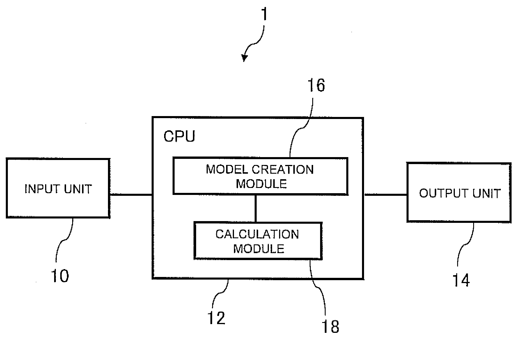
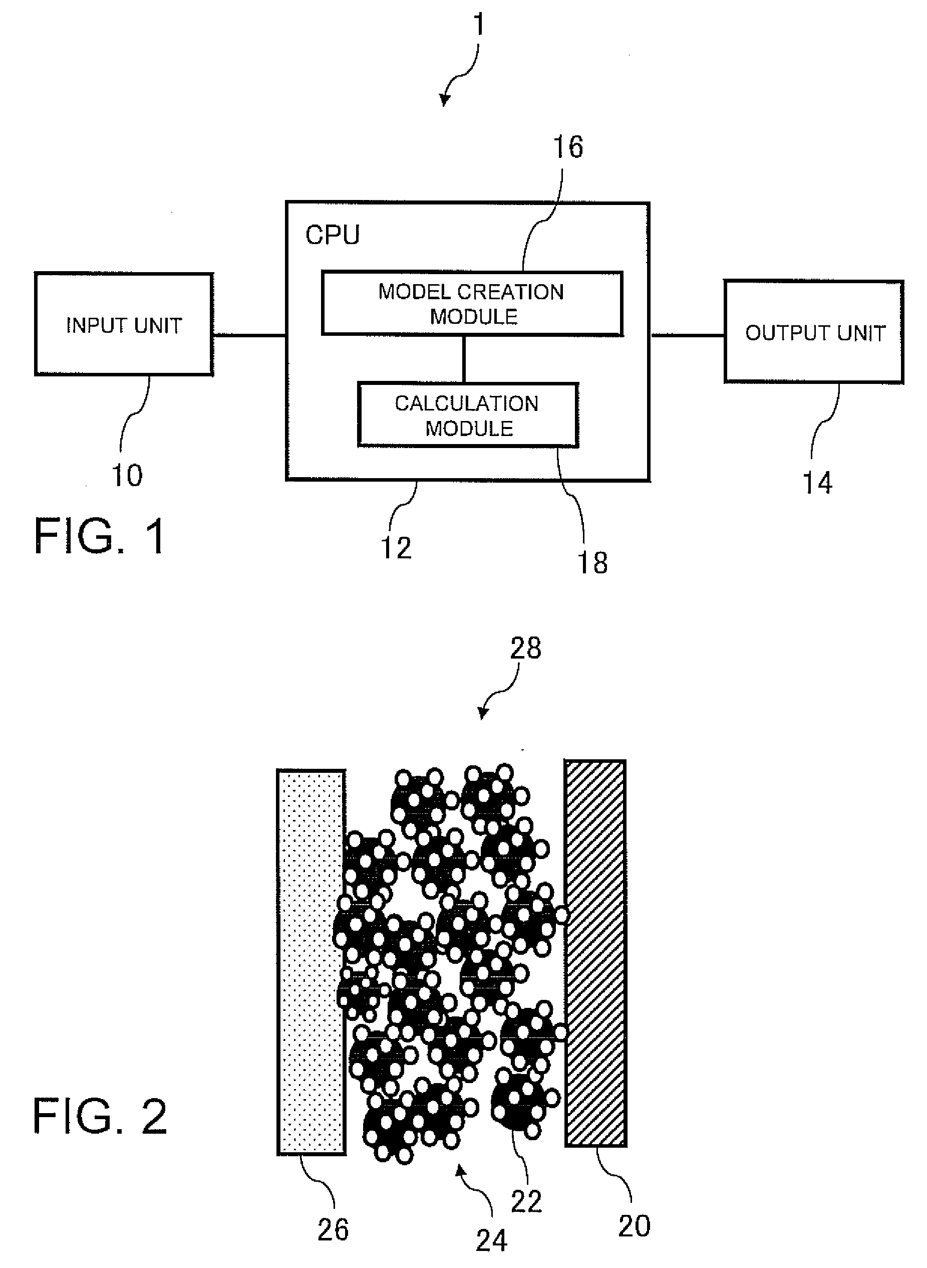
[0024]FIG. 1 is a view schematically illustrating an example structure of a fuel cell simulator according to an embodiment of the present invention. As illustrated in FIG. 1, a fuel cell simulator 1 includes an input unit 10 such as a keyboard for inputting geometry and property value data of a catalyst layer, an electrolyte membrane, and a diffusion layer (which will, in some instances, be collectively referred to as a catalyst layer and so on), a CPU 12 which executes operation processing, and an output unit 14 such as a display for outputting a calculation result.

[0025]The CPU 12 includes a model creation module 16 for modeling the catalyst layer and so on from geometry and property data of the catalyst layer and so on. The model creation module 16 of the CPU 12 uses 3D solid CAD such as CATIA or a voxel method to model the catalyst layer and so on from the geometry and physical ...


PUM


Abstract

Disclosed is a fuel cell simulator for predicting the power generation performance of a fuel cell including a membrane-electrode assembly having an electrolyte membrane, a catalyst layer, and a diffusion layer. The fuel cell simulator includes a model creation unit for modeling a catalyst layer from the geometry and property data of the catalyst layer, and a calculation unit for calculating the power generation state distribution of the catalyst layer or macro physical property values by using the catalyst layer model and establishing simultaneous equations of gas transportation, water production-transportation phase change, electrical conduction, heat conduction, and catalytic reaction.

Description

TECHNICAL FIELD[0001]The present invention relates to a fuel cell simulator for predicting power generation performance of a fuel cell, and a fuel cell which is designed by using a prediction result of the fuel cell simulator.BACKGROUND ART[0002]As one of countermeasures against environmental problems in recent years, in particular global warming associated with air pollution and generation of carbon dioxide caused by gas emission of motor vehicles, fuel cell technologies which enable clean emission and highly energy-efficient driving have attracted attention. A fuel cell is formed of a membrane-electrode assembly including an electrolyte membrane, a pair of catalyst layers sandwiching the electrolyte membrane, and a pair of diffusion layers further sandwiching both outer surfaces of the catalyst layers, and a pair of fuel cell separators disposed on both outer surfaces of the membrane-electrode assembly.[0003]Because the above-described elements forming a fuel cell are expensive, s...

Claims


Application Information

Patent Timeline
IPC IPC(8): H01M8/04G06G7/62
CPCH01M4/86Y02E60/50H01M8/04305Y02P70/50
Inventor FUJIUCHI, MAKOTOIDA, ATSUSHIHARADA, TAKASHIKAWAMOTO, TADASHI
Owner TOYOTA JIDOSHA KK
Why Eureka
Try Eureka