

Burner for manufacturing porous glass base material
- Summary
- Abstract
- Description
- Claims
- Application Information
AI Technical Summary
Benefits of technology
Problems solved by technology
Method used
Image

Examples
embodiments
Preliminary Investigation
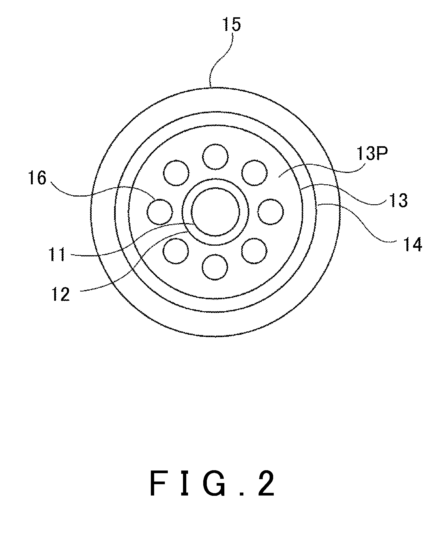
[0046]First, in the preliminary investigation, variation of linear velocity at the tip of a conventional burner, such as shown schematically in FIGS. 2 and 3, was measured for each gas discharge port.
[0047]This burner has a coaxial pipe structure, wherein eight small-diameter gas discharge port nozzles 16 are contained in a third pipe 13 and these small-diameter gas discharge port nozzles 16 are arranged at uniform intervals in a circle centered on a central pipe 11. As shown in FIG. 3, a small-diameter gas discharge port nozzle 16 is formed to branch from the burner main pipe 18 at a position, shown by the reference numeral 17, that is L=80 mm from the burner tip.
[0048]A gas for manufacturing porous glass base material was supplied to pipes other than the central pipe 11 of the burner, and a hot wire anemometer was used to measure the variation of linear velocity at the burner tip at a normal temperature. The gas was N2 supplied as a sealing gas to the seco...
first embodiment
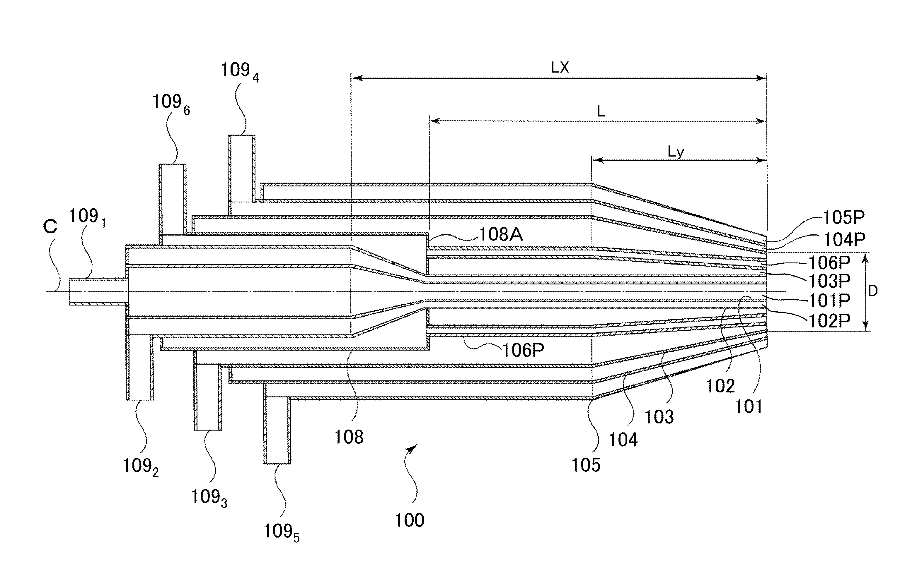
[0051]FIG. 7 is used to describe a burner 100 having a structure of five coaxial pipes according to an embodiment of the present invention. In this burner 100, eight small-diameter gas discharge port nozzles 106N are contained in a third pipe 103, the small-diameter gas discharge port nozzles 106N are arranged to branch from the main pipe 108 at a position that is L=80 mm from the burner 100 tip as shown in FIG. 7, the aperture diameter of the third pipe 103 is 40 mm, and L / D=2.0.
[0052]The first pipe 101 and second pipe 102, which are farther inward than the small-diameter gas discharge port 106P, have inner diameters that begin contracting to be 83% of their original size at a certain distance, i.e. a length Lx=120 mm, from the burner 100 tip, and the third to fifth pipes farther outside from the small-diameter gas discharge port 106P have inner diameters that begin decreasing to be 83% of their original size at a certain distance, i.e. a length Ly=40 mm, from the burner 100 tip. T...
second embodiment
[0059]The length L of the small-diameter gas discharge port nozzles 106N of the burner 100′ with L / D=1.5 used in Comparative Example 1 was changed while keeping the same burner source diameter, burner tip diameter, and contraction position to obtain a burner 100″ having a different L / D ratio between the length L of the small-diameter gas discharge port nozzles 106N and the aperture diameter D of the third pipe 103. Next, 100 kg of glass fine particles were deposited on a starting member that was formed by fusing dummy rods with outer diameters of 50 mm to the ends of a core rod that has a length of 2000 mm and an outer diameter of 50 mm. FIG. 13 shows the relationship between L / D and the deposition efficiency.
[0060]In the burner 100″, the first pipe 101 was supplied with SiCl4 as the glass raw material at 10 L / min and O2 as an auxiliary combustion gas at 20 L / min, the second pipe 102 was supplied with N2 as a sealing gas at 4 L / min, the third pipe 103 was supplied with H2 as a combu...
PUM
| Property | Measurement | Unit |
|---|---|---|
| Length | aaaaa | aaaaa |
| Diameter | aaaaa | aaaaa |
| Distance | aaaaa | aaaaa |
Abstract
Description
Claims
Application Information