Endoscope-pipe

a technology of endoscope and pipe, which is applied in the field of endoscope pipes, can solve the problems that endoscope pipes, in fact, typically demonstrate an unpleasantly non-homogeneous illumination of the working area, and achieve the effects of good brightness, high reliability and good observation of the working area

Active Publication Date: 2010-12-23
KARL STORZ GMBH & CO KG
View PDF11 Cites 16 Cited by
  • Summary
  • Abstract
  • Description
  • Claims
  • Application Information

AI Technical Summary

Benefits of technology

[0007]A surprising discovery has been the fact that through an appropriate choice of arrangement or configuration of the light outlet openings around the elongated observation window, which is centrally positioned on the distal end of the endoscope pipe, it becomes possible to have a clearly improved and largely homogeneous illumination of the observed angle of vision, which need not necessarily contain the entire optical acquisition area.
[0009]As a result of the inventive arrangement of the light outlet openings exclusively along the longitudinal extension of the observation windows, a relatively high number of outlet openings can successfully be selected and thereby a very good brightness can be achieved with good homogeneity in accordance with the invention. The inventive endoscope pipe thus proves itself well suited for difficult operations that require a highly reliable and good observation of the working area. The two aforementioned concepts have proved especially advantageous—first, the non-homogeneous distribution of the light outlet openings along the longitudinal extension of the observation windows and, second, the non-homogeneous selection of emission directions from the fiberoptic end surfaces of the light outlet openings. Through this combination, an especially efficient and homogeneous illumination of the relevant working area becomes possible. In addition, through this combination, the advantages of both concepts can be linked and moreover a decidedly closer arrangement of the light outlet openings becomes possible, along with either a reduction of the diameter of the endoscope pipe in case of predetermined light quantity for illuminating the relevant working areas, or conversely, in case of a predetermined diameter of the endoscope pipe, an increased light quantity. Either situation results in an increase in the possible application area of the inventive endoscope pipe compared with the endoscope pipe previously known in the art.
[0010]It has proved especially effective here to determine the emission direction for the light from the light outlet openings on the basis of having a prism or a holographic element positioned in the area of the fiberoptic end surfaces, by means of which the desired modification of the emission direction in relation to the light outlet opening from the fiberoptic end surface is determined. Owing to this arrangement of a prism or of a holographic element, it becomes possible, in a very defined and predetermined manner through the choice of prism or the configuration of the holographic element, to ensure a reliable and secure diversion of the light beam emerging from the fiberoptics into the desired direction for creating a distribution that is as homogeneous as possible. It has also proved effective here to use a prism or a holographic element for several neighboring fiberoptic end surfaces together. Consequently, on the one hand, it is possible to achieve a very compact structure and simple manufacturing along with secure, uniform deflection. The result is a very cost-effective realization of the inventive endoscope pipe. Alternatively or in addition, it has proved effective to configure the end surfaces of the fiberoptic or fiberoptics in such a way that the surface cuts the longitudinal axis of the fiberoptic at an angle not equal to 90 degrees. Through the choice of angle, a well-defined deflection of the emerging light becomes possible into the desired direction, varying according to the light outlet opening. It has proved especially advantageous here to combine several fiberoptics into one fiberoptic bundle and to cement them together in the light outlet opening and to configure the end surface of this bundle of fiberoptic ends and cement in such a way, in particular through cutting, that the surface becomes flat in part, and the desired angle of the fiberoptic end surfaces is achieved with respect to the longitudinal extension of the fiberoptics. This configuration ensures, on the one hand, that end surfaces very efficiently enable the transition from the optically thicker material to the environment in the desired emission direction and, on the other hand, that that there is a strongly insulated sealing of the light outlet opening and thereby of the interior space of the endoscope pipe. Thanks to this inventive insulating effect, sterilization in the manner of autoclaving finally becomes a realistic possibility.
[0011]It has proved especially advantageous to position the prism or prisms, or the holographic element or elements, between the fiberoptic end surfaces and the light outlet openings, and to cement these as a unit together with the fiberoptics. It has proved effective here to use an optically inactive cement that has an index of refraction corresponding to that of the fiberoptics or of the prism or of the holographic element.
[0012]The observation window is advantageously in the form of a domed observation window, in particular with a cylindrical dome, because the shaft is domed in the direction of the longitudinal extension of the shaft. This configuration makes it possible to increase the length of the observation window and thereby the area for positioning the light outlet openings and consequently to ensure a more extensive homogeneous illumination of the working area in the area in front of and to the sides of the distal end of the endoscope. As a result of the domed configuration of the endoscope window, the observation range of the endoscope is also considerably enlarged through the corresponding configuration of the lens below the observation window. The result is a very effective and useful endoscope pipe.
[0013]Container sleeves are preferably provided in the light outlet surfaces, to direct the fiberoptics and fiberoptic end surfaces which in turn allows an adjustment of the desired emission direction of the light from the light outlet openings in simple, reliable manner.

Problems solved by technology

These known endoscope pipes, in fact, typically demonstrate an unpleasantly non-homogeneous illumination of the working area, specifically in their use of non-circular illumination windows.

Method used


Image

  • Endoscope-pipe
  • Endoscope-pipe
  • Endoscope-pipe

Examples


Embodiment Construction

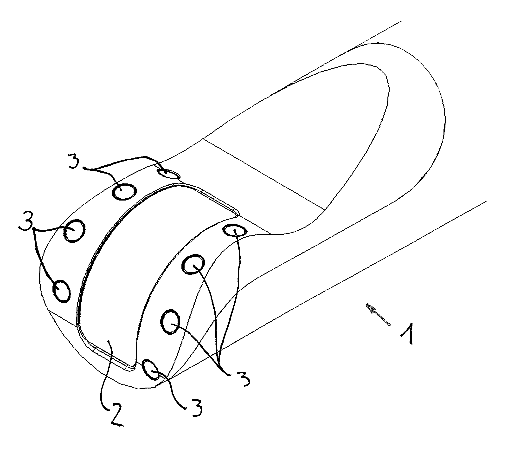
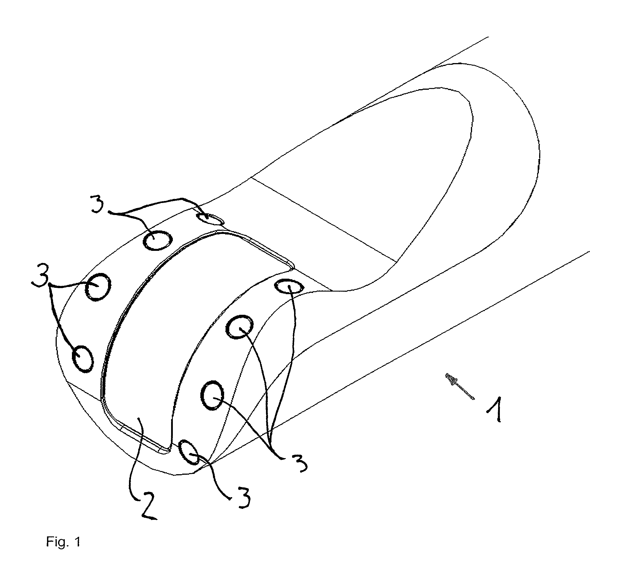
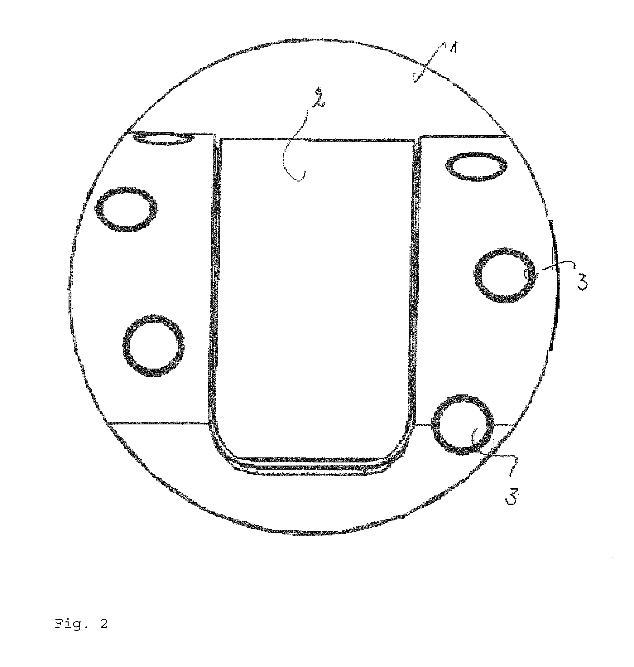
[0018]FIG. 1 shows in a diagonal view the distal end 1 of the inventive endoscope pipe. Shown at the center is the observation window 2, which is longitudinally extended in configuration and is positioned at the center in the area of the distal end 1. The observation window 2 here is configured as continuously domed, so that the dome extends similarly to a cylinder in the longitudinal direction of the endoscope pipe. The observation window here shows an essentially rectilinear shape, which is configured as essentially cylindrically domed.

[0019]The light outlet openings 3 are positioned along the longitudinal extension of the observation window 2. There are a total of eight light outlet openings, which are positioned opposite one another and asymmetrically to the longitudinal extension of the longitudinal axis of the observation window. They are placed at varying distances from the longitudinal axis or are offset in alternation along the longitudinal axis of the observation window 2....


PUM


Abstract

An endoscope pipe with a central, elongated observation window on the distal end, whereby several light outlet openings for fiberoptic end surfaces are positioned close to the observation window for illuminating the angle area observed through the observation window and the light outlet openings are positioned asymmetrically in relation to the longitudinal extension of the observation window and / or the fiberoptic end surfaces are held in the light outlet openings in such a way that light is beamed from the fiberoptic end surfaces into the angle area in various directions.

Description

CROSS-REFERENCE TO RELATED APPLICATIONS[0001]The present application claims priority of German patent application No. 10 2009 025 659.8 filed on Jun. 17, 2009.FIELD OF THE INVENTION[0002]The invention relates to an endoscope pipe. Endoscope pipes are parts of endoscopes that have applications especially in the field of minimally invasive surgery on humans or animals and, in rare cases, also in the field of technology.BACKGROUND OF THE INVENTION[0003]There are known endoscopes in the art that are configured in tubular form with pronounced length and are equipped on their distal end with an observation window, through which, in the case of an operation, it is possible to look into the surgical area situated in front of the distal end. Endoscopic instruments to perform surgical manipulation in the operating area can be inserted in the endoscope pipe through optional additional working channels. In addition, the end of the endoscope pipe comprises one or more light outlet openings, whic...

Claims


Application Information

Patent Timeline
Patent Type & Authority Applications(United States)
IPC IPC(8): A61B1/07
CPCA61B1/00096A61B1/00167A61B1/00179G02B23/2469A61B1/0623A61B1/07G02B23/2423A61B1/0607A61B1/0625A61B1/0615A61B1/0676G02B5/32G02B23/02
Inventor LEI, FANGWEIGER, ULRICH
Owner KARL STORZ GMBH & CO KG
Why Eureka
Try Eureka