Arthroscopic fluid control device and method for controlling fluid flow in arthroscopic procedures

a technology of fluid control device and arthroscopic procedure, which is applied in the field of arthroscopic fluid control device and method for controlling fluid flow in arthroscopic procedures, can solve the problems of high initial cost plus maintenance cost of mechanical pumps, high initial cost plus maintenance cost, and electric conduction injury, so as to prevent the collapse of a joint space, facilitate control, and maintain clear visualization

Active Publication Date: 2010-12-23
REZNIK ALAN M
View PDF17 Cites 27 Cited by
  • Summary
  • Abstract
  • Description
  • Claims
  • Application Information

AI Technical Summary

Benefits of technology

[0005]The fluid control device is attached to tubes carrying irrigation solution to form the system. The control device splits the flow through a fiber optic scope and a fluid control unit. The fluid control unit controls rate of flow and direction. The flow of fluid into the joint, out of the joint, or no flow is easily controlled by the operator. The device also allows for one or more inflows, and or more than one outflow. This is useful when using suction or suction shaving devices or when the joint space is small and fluid rate or direction control can aid in visualization. The increased flow prevents collapse of a joint space and maintains clear visualization. The fluid flow relies on gravity by having a fluid reservoir positioned at a high point in the system. The device can be configured in a number of novel ways to provide fluid control for rate and direction into and out of any number of cannulas, ports, or arthroscopic instruments. The fluid can be provided by a single or multiple fluid bags or reservoirs.

Problems solved by technology

Mechanical pumps have high initial costs plus maintenance costs and there is always the possibility that, during surgery, a pump will fail.
There is always a risk of electric conduction injury and a risk of compartment syndrome where fluid pressure in a compartment exceeds venous pressure causing a loss of circulation to a limb or muscle group.
This risk can be even greater with some of the current mechanical fluid systems when fluid leaks into spaces outside the joint as occurs in acute trauma when there is communication between the joint and local soft tissue.
More recently electronic controls for fluid devices have been shown to have faulty electronics and / or problematic software leading to FDA recalls of these devices, mandatory service calls or upgrades to avoid patient injury.
These concerns raise the inherent cost of these devices and add the requirement of significant post-market surveillance while in use.

Method used


Image

  • Arthroscopic fluid control device and method for controlling fluid flow in arthroscopic procedures
  • Arthroscopic fluid control device and method for controlling fluid flow in arthroscopic procedures
  • Arthroscopic fluid control device and method for controlling fluid flow in arthroscopic procedures

Examples


Embodiment Construction

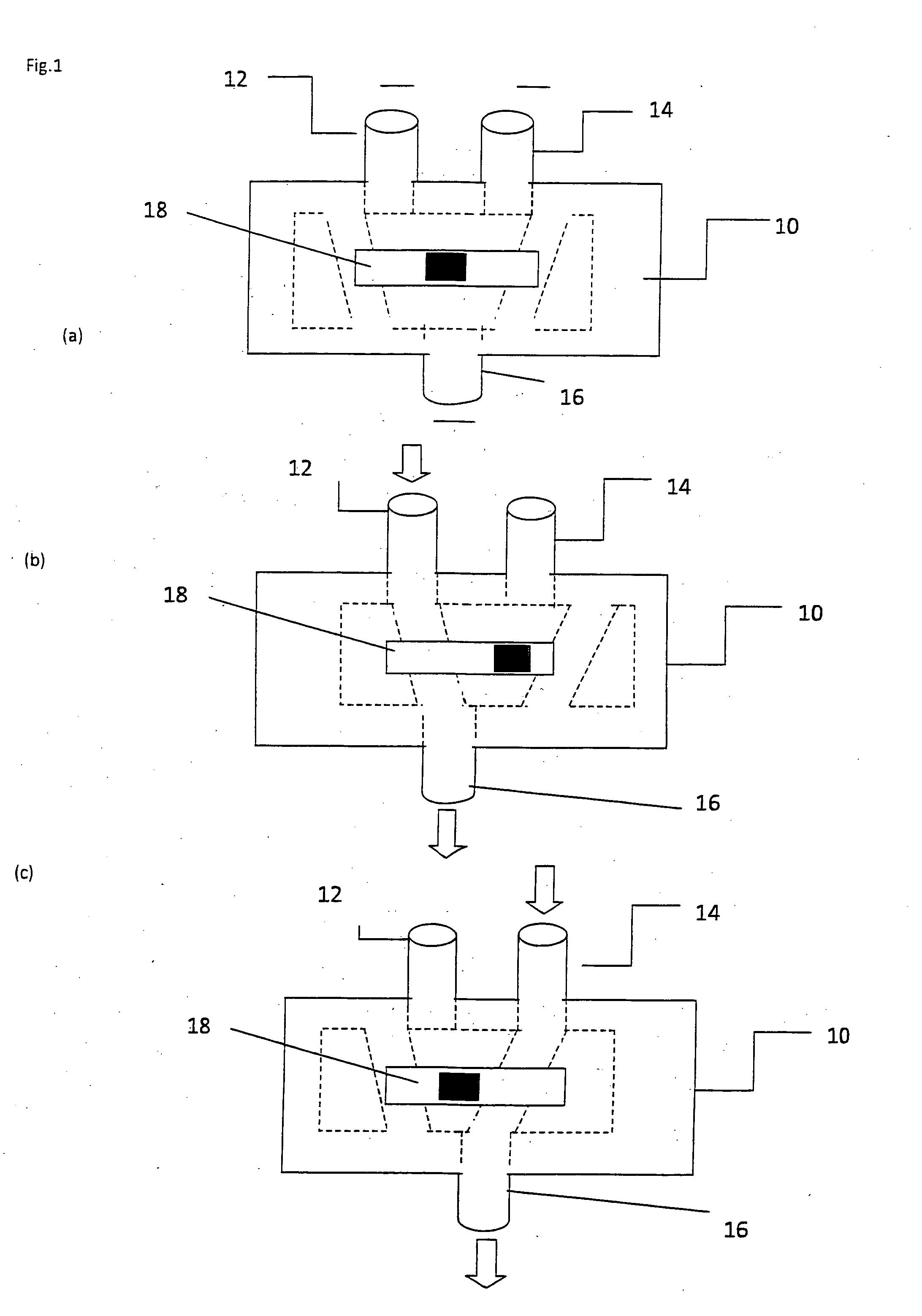
[0026]FIG. 1 shows a fluid control device 10 having three ports 12, 14, 16. A slider is positioned between the two ports 12, 14. In FIG. 1A, the slider 18 is in the central position and there is no fluid communication between any ports. In FIG. 1B, the slider is moved to the right position and fluid flows between ports 12 through port 16. In FIG. 1C, a slider is moved to the left position and there is fluid communication between the port 16 and port 14.

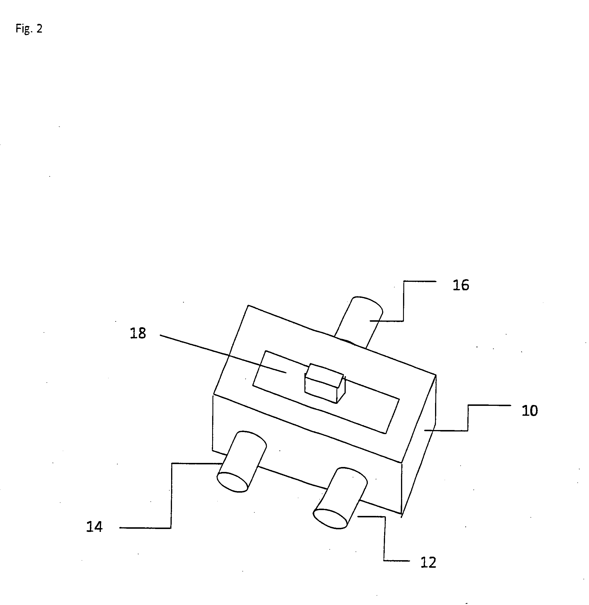
[0027]FIG. 2 shows the front rear end perspective view of the fluid control device. In the front view, the slider and port 16 are seen. In the rear view, the ports 12 and 14 are seen, as well as the slider. This perspective view shows all three ports 12, 14, 16 and the slider 18.

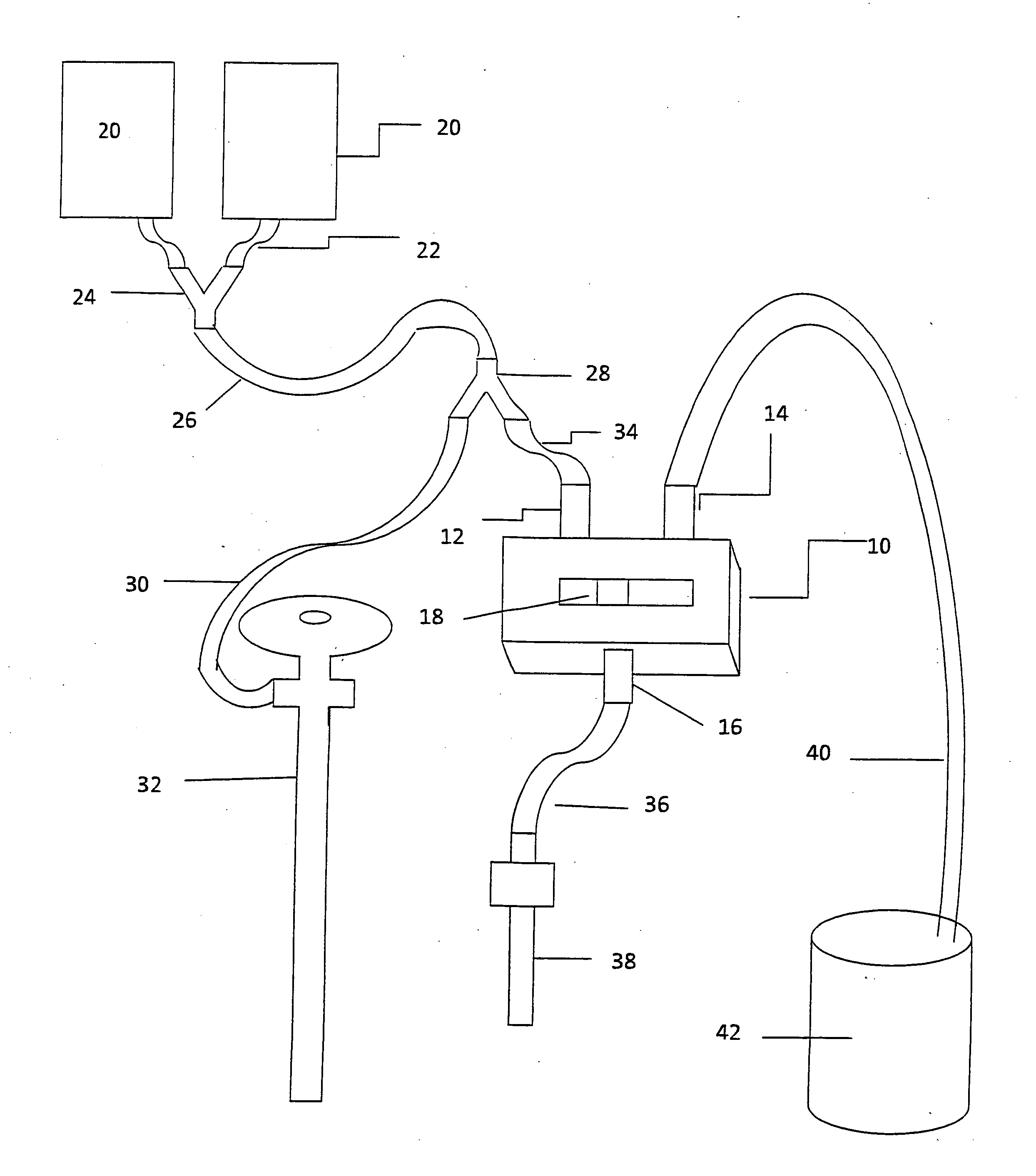
[0028]FIG. 3 shows the complete fluid control system, with fluid reservoirs 20 each having an outlet line 22 connected to a fluid divider, such as a Y junction 24, with line 26 leading from the Y junction 24 to a second Y junction 28. A single reservoir may be...


PUM


Abstract

A fluid control device is attached to tubes carrying irrigation solution to form the system. The control device splits the flow through a fiber optic scope and a fluid control unit. The fluid control unit controls rate of flow and direction. The operator utilizing a fluid rate and flow direction control device easily controls the flow of fluid into the joint, out of the joint, or no flow. The increased flow prevents collapse of a joint space and maintains clear visualization. The fluid flow solely relies on a gravity feed by having a fluid reservoir positioned at a high point in the system. It contains no fluid pump, vacuum or electronic controller while safely and reliably performing the functions of more complex devices.

Description

[0001]This application claim benefit of provisional application 60 / 789,598, filed Apr. 6, 2006, and U.S. patent application Ser. No. 11 / 730,944 filed Apr. 5, 2007.BACKGROUND OF THE INVENTION[0002]During arthroscopic surgery the flow of fluids and suction to the site must be controlled based on the surgeon's needs. Normally, fluid control is achieved with the use of a mechanical pump. Mechanical pumps have high initial costs plus maintenance costs and there is always the possibility that, during surgery, a pump will fail. There is always a risk of electric conduction injury and a risk of compartment syndrome where fluid pressure in a compartment exceeds venous pressure causing a loss of circulation to a limb or muscle group. This risk can be even greater with some of the current mechanical fluid systems when fluid leaks into spaces outside the joint as occurs in acute trauma when there is communication between the joint and local soft tissue. The invention gravity controlled positive...

Claims


Application Information

Patent Timeline
Patent Type & Authority Applications(United States)
IPC IPC(8): A61M1/00
CPCA61B1/015A61B1/12A61M2039/224A61M3/0241A61B1/317Y10T137/86493A61M3/022A61M3/0208A61M3/0212A61M3/0202
Inventor REZNIK, ALAN M.
Owner REZNIK ALAN M
Why Eureka
Try Eureka