Fishing apparatus

a technology of fishing equipment and hooking rods, which is applied in fishing, other angling devices, animal husbandry, etc., can solve the problems of poor hooking ratio and difficulty in removing fish from the lur

Inactive Publication Date: 2010-12-30
WEBB RICHARD
View PDF43 Cites 3 Cited by
  • Summary
  • Abstract
  • Description
  • Claims
  • Application Information

AI Technical Summary

Benefits of technology

[0009]According to an aspect of the invention there is provided a bait assembly for fishing comprising a hook coupled to a rearward end of a line; a bait body moveably mounted with respect to the line and arranged so that in normal use a flexible section of the line extends into the bait body (e.g. through an aperture) and a retaining mechanism arranged to bias

Problems solved by technology

In other examples, the hook can be attached to the lure body in a manner that does not allow it to move about its attachment point.
In addition to the poor hook-up-ratio, there are other practical problems with conventional lures such as

Method used


Image

  • Fishing apparatus
  • Fishing apparatus
  • Fishing apparatus

Examples


first embodiment

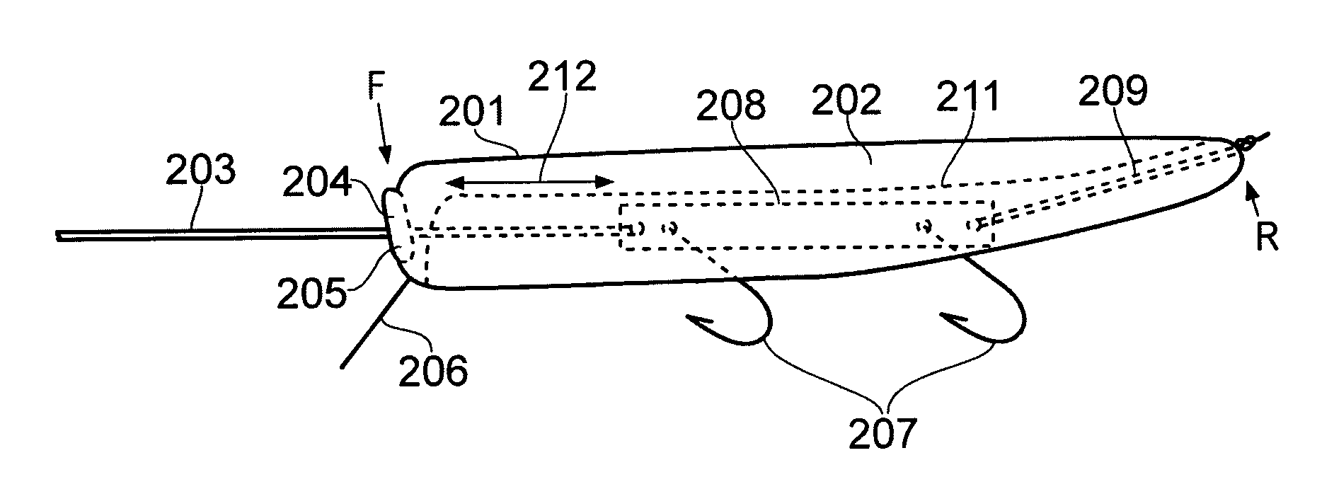
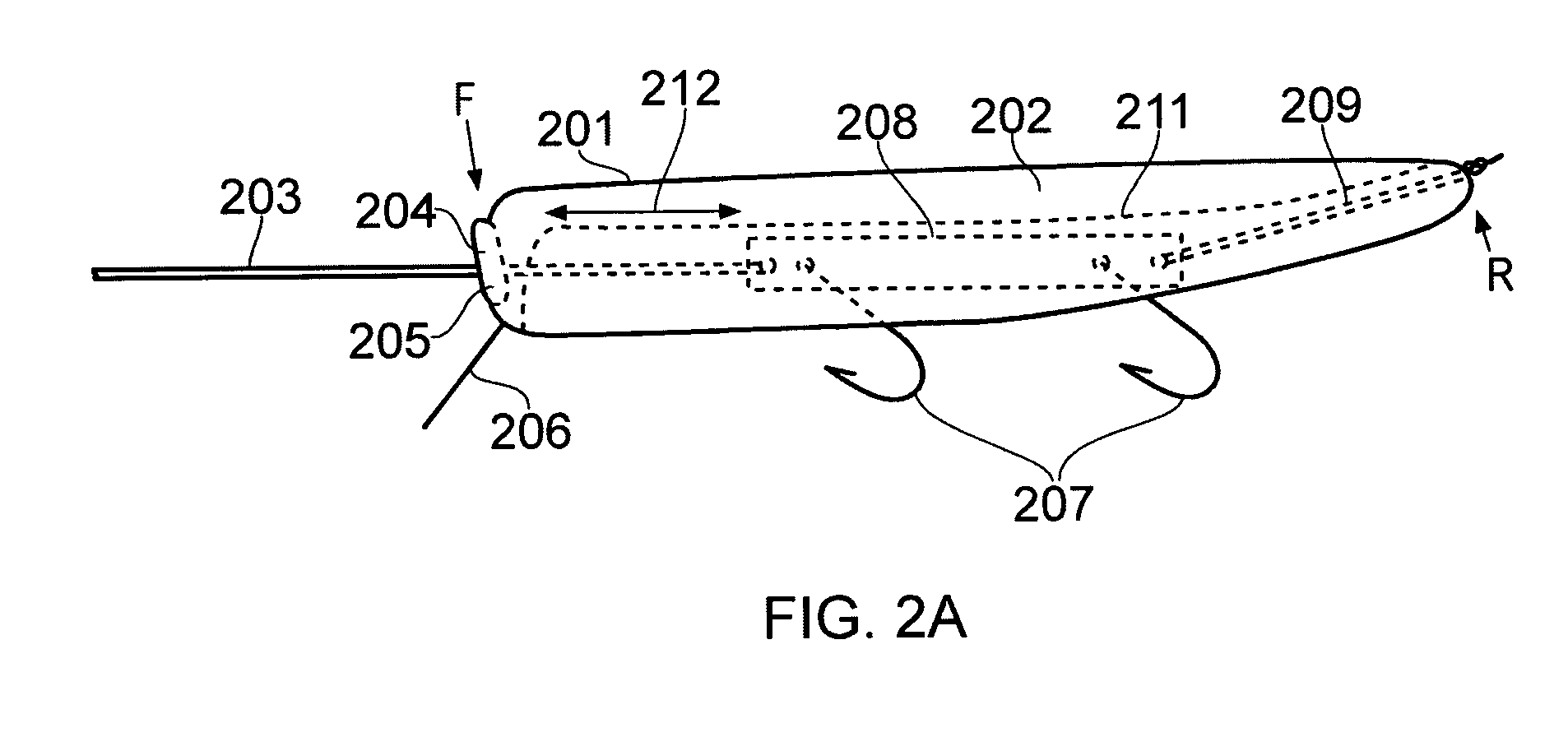
[0037]FIG. 2A shows a fishing apparatus 201 according to the invention. The fishing apparatus 201 comprises a lure body 202 having a forward end (generally indicated at F to the left in FIG. 2A) and a backward end (generally indicated at R in FIG. 2A). The lure body 202 in this example is made from wood and is painted as desired to attract fish, e.g. in a similar manner to how conventional lure might be painted. Other lure body materials could be used, e.g., plastics or metals. The lure body 202 may be weighted so that it sinks to a desired depth, or may be buoyant so that it floats. The overall characteristic lure body size and shape may generally accord with those of conventional lures (i.e. will be selected primarily according to what is considered most likely to attract fishes sought). The example lure body in FIG. 2A is generally elongate having an overall rounded square outer profile, and has a length of around 10 cm and a characteristic width of around 2.5 cm. Other shapes ma...

second embodiment

[0053]FIG. 3A shows a fishing apparatus 301 according to the invention. This embodiment differs from the embodiment shown in FIGS. 2A to 2D primarily by using a different retaining device / biasing mechanism. Whereas the example in FIGS. 2A to 2D employs an elastic string, the embodiment shown in FIG. 3A uses a spring. What is more, the spring in FIG. 3A is arranged to operate in compression (rather than extension) when the hooks move forward. Many aspects of the fishing apparatus 301 shown in FIGS. 3A and 3B are similar to and will be understood from the above description of the fishing apparatus 201 shown in FIGS. 2A to 2D.

[0054]Thus the fishing apparatus 301 comprises a lure body 302, having a forward and backward end. The forward end of the lure body comprises an aperture 307 arranged to accommodate a friction fit plug 305. The friction fit plug 305 is inserted into the aperture 307 but may be readily removed if desired, as described further below. The friction fit plug 305 furthe...


PUM


Abstract

A bait assembly for fishing, e.g. leisure fishing, is described. The bait assembly comprises a hook coupled to a rearward end of a line. A bait body is slideably or detachably mounted with respect to the line so that in normal use a flexible section of the line extends into the bait body. The bait body may comprise an artificial lure, or may comprises a skewer onto which dead bait may be mounted. A retaining mechanism is arranged between the bait body and the line to bias the bait body in a forward position on the line relative to the hook. Thus when a pulling force is applied between the bait body and the line which overcomes the biasing action of the retaining mechanism, the bait body is operable to move backwards with respect to the line (e.g. by sliding or breaking free), thereby causing a relative forward translational movement of the hook with respect to the bait body. Accordingly, when a fish bites onto the bait body in use, the resulting increased pulling force on the bait body relative to the line causes the hook to move/slide forward in the fish's mouth relative to the bait body. This leads to an increased likelihood of the fish being hooked and so thus providing for an increased hook-up-ratio.

Description

BACKGROUND ART[0001]The present invention relates to a fishing apparatus, and in particular to a bait assembly for a fishing apparatus.[0002]Bait, e.g., for leisure fishing, typically comprises a bait body and a hook (or hooks) which are together attached to a fishing line. The bait is designed to attract a fish such that the fish bites on the bait body and becomes caught on the hook. The bait may be artificial bait, e.g. a lure, or may be dead bait, e.g. using a dead fish as a bait body.[0003]An artificial lure typically comprises a generally elongate lure body having a front end for coupling to a fishing line, and a hook fixedly attached to a body of the lure at a position along its length, e.g. at a trailing (rear) end of the lure body, or at a position midway along the lure body's axis of extent. The hook is typically attached to the lure body in a manner that allows the hook to move freely about its attachment point. For example, a split ring could be used to attach the hook to...

Claims


Application Information

Patent Timeline
IPC IPC(8): A01K85/00
CPCA01K85/02A01K97/18A01K91/10A01K85/16A01K85/00A01K85/18
Inventor WEBB, RICHARD
Owner WEBB RICHARD
Why Eureka
Try Eureka