Efficient RF Electromagnetic Propulsion System With Communications Capability

Active Publication Date: 2010-12-30
MCLEAN JOHN P +1
View PDF11 Cites 58 Cited by
  • Summary
  • Abstract
  • Description
  • Claims
  • Application Information

AI Technical Summary

Benefits of technology

[0017]This invention has a number of advantages over other advanced propulsion concepts. One important advantage is that this form of propulsion requires only electrical power for operation. No supply of propellant is required, thus it has an infinite specific impulse. From simulation data, this invention also appears to be much more efficient than any current or proposed advanced propulsion concepts that we are aware of (including photon, ion & plasma). It can be used for deep space propulsion and possibly within the atmosphere. This invention can operate in complete silence, and without any disturbances to its surroundings. It appears possible to build air and space vehicles using said systems that do not require aerodynamic forces: uses no wings, props or jet exhausts, can operate in confined spaces, can operate in highly turbulent a

Problems solved by technology

This imbalance results in a force on the system of the two magnets similar to the thrust produced by a jet or rock

Method used


Image

  • Efficient RF Electromagnetic Propulsion System With Communications Capability
  • Efficient RF Electromagnetic Propulsion System With Communications Capability
  • Efficient RF Electromagnetic Propulsion System With Communications Capability

Examples


embodiment

Preferred Embodiment

Description and Operation—FIGS. 6A, 6B, 6C, 6D and 7

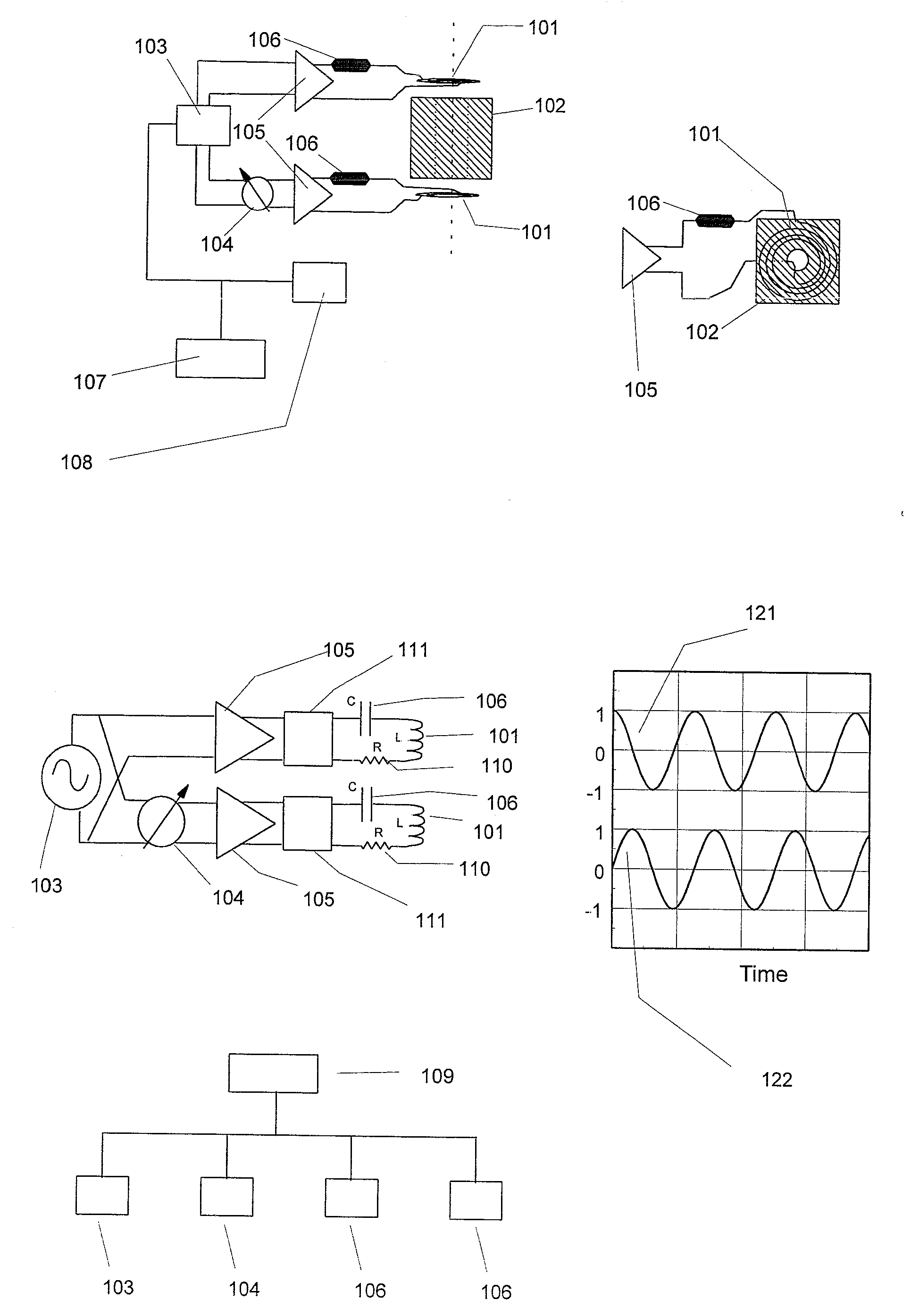
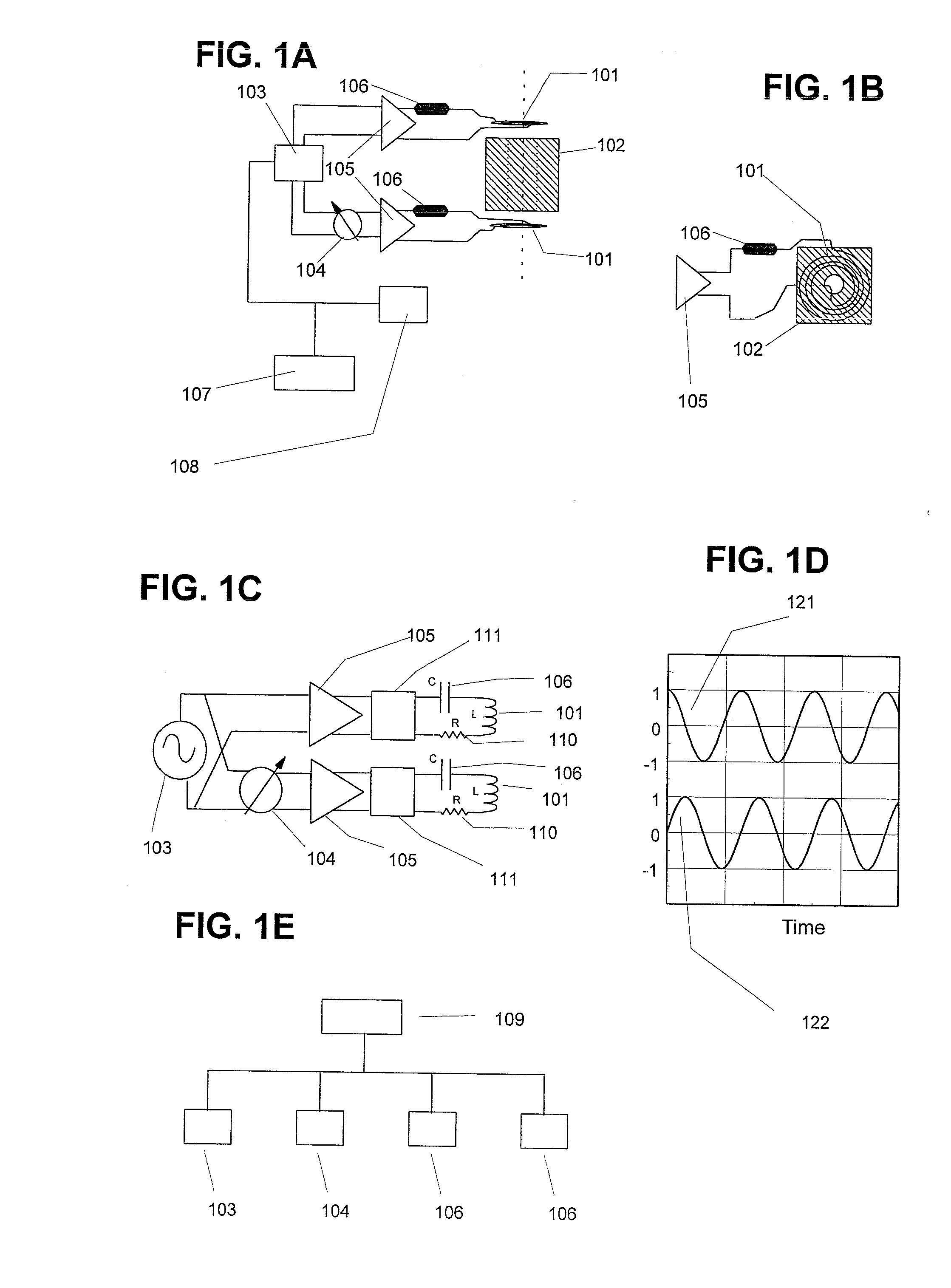
[0096]This embodiment is derived from the basic embodiment, with the addition of auxiliary tuning circuits (FIG. 3A, 301) and the back-to-back EM coils design (FIG. 5). The use of RF superconducting wiring is also a candidate for use. This embodiment is shown in FIG. 6A through 6D and FIG. 7. FIGS. 6A and 6B show side and top views for the principal components for a basic building block for this embodiment. FIG. 6C shows an expanded 3D view of this block, while FIG. 6D shows a module that is made from multiple blocks. This embodiment is composed of four EM coils 101, each with its supporting electronics circuit board 601 and three spacer cores 102. The four circuit boards are identical except for their input signal phases and their placement around the system. This placement reduces the lengths of connecting wire segments and minimizes circuit impedances. The use of four systems is a convenient module size that ...


PUM


Abstract

An electronic propulsion engine that creates a propulsive force or thrust using electromagnetic forces or electrostatic forces, with an effect that is similar to the thrust of a jet or rocket engine. Forces are generated using electromagnets or capacitor plates that are separated by dielectric spacer cores and are operated with two modulated currents. The two modulated currents are synchronized, but with a relative phase such that the forces on the two magnets or capacitor plates are not balanced. Included are techniques to reduce circuit impedance and control electric-magnetic field dispersion, such as tuned LCR circuits, dielectric core materials between the magnets or capacitor plates, and RF superconductors result in high propulsion efficiencies. The system operates at RF frequencies and can also be used as a communication device.

Description

CROSS REFERENCE TO RELATED APPLICATIONS[0001]The present application claims priority from an earlier filed provisional patent application Ser. No. 61 / 200,202, filed Nov. 25, 2008, by the same inventors.BACKGROUND OF THE INVENTION[0002]1. Field of the Invention[0003]The present invention generally relates to propulsion technologies for use with space, air and other vehicles; more specifically to a propulsion system based entirely on electric and electromagnetic forces, and including methods that provide high efficiency.[0004]2. Description of the Prior Art[0005]The following references represent the closest prior art known to Applicants at the time of the filing of the present application:[0006]US Patent Documents:5,142,861September 1992USA5,197,279March 1993USA6,492,784December 2002USA7,190,108April 2007USA[0007]Foreign Patent Documents:1586195February 1970France2036646December 1970France58-32976(A)February 1983Japan1268467A2October 1989Japan[0008]Of the above references, the closes...

Claims


Application Information

Patent Timeline
IPC IPC(8): F03H1/00
CPCF03H99/00
Inventor MCLEAN, JOHN P.MCLEAN, DAVID R.
Owner MCLEAN JOHN P
Why Eureka
Try Eureka