
Tire Treatment Device with Shock Absorption and Vehicle Misalignment Tolerance

Active Publication Date: 2010-12-30
PISTON OPW INC
View PDF8 Cites 3 Cited by
  • Summary
  • Abstract
  • Description
  • Claims
  • Application Information

AI Technical Summary

Benefits of technology

[0007]In the preferred embodiment, the applicator system is used in combination with outwardly angled i.e., diverging, vehicle entry guides. The system pre-orients the opposing applicator structures in a mirror-image arrangement in which the entry ends are closer together than the exit ends and the tire guides diverge outwardly to capture the leading edges of the front tires of a vehicle even if that vehicle is seriously misaligned with respect to a centerline designating a preferred entry orientation / position of a vehicle to be treated. A system of cylinders provides resilience in the two structures, whereby initial contact between the leading edge of the tires of the vehicle and the tire guide rails attached to the applicator structures causes the applicator structures to move as necessary to absorb shock and to position the applicators where they will enjoy perfect contact with the sidewalls of a vehicle entering and passing through the treatment station. Limit stops are provided on the structure to prevent excessive flexing and / or angular reorientation. The overall length of the system is such that at least 180° of tire rotation is required to traverse the entire length of the applicator and most vehicles will have both front and rear tires in contact with the applicator pads at the same time for at least a brief portion of the overall tire treatment process.

Problems solved by technology

However, as disclosed, the support systems for the aforementioned applicator structures are less suitable for conveyorless, drive-through car wash installations where it is up to the driver of each vehicle to orient and align the vehicle with a designated path of travel while entering and passing through the tire dressing applicator station; i.e., some drivers tend to favor one side of the vehicle over the other while other drivers provide steering inputs which result in undesired changes in vehicle alignment prior to or during a treatment process.
It has been found that either causing the vehicle to enter the station off-center or creating a misalignment between the longitudinal axis of the vehicle and the desired center line of the treatment station can cause poor results in the treatment process and / or damage to the equipment in the car wash.
This is because the support system for the treatment station as shown in the aforementioned application, is not tolerant of high degrees of off-center entry or travel and / or misalignment.

Method used


Image

  • Tire Treatment Device with Shock Absorption and Vehicle Misalignment Tolerance
  • Tire Treatment Device with Shock Absorption and Vehicle Misalignment Tolerance
  • Tire Treatment Device with Shock Absorption and Vehicle Misalignment Tolerance

Examples


Embodiment Construction

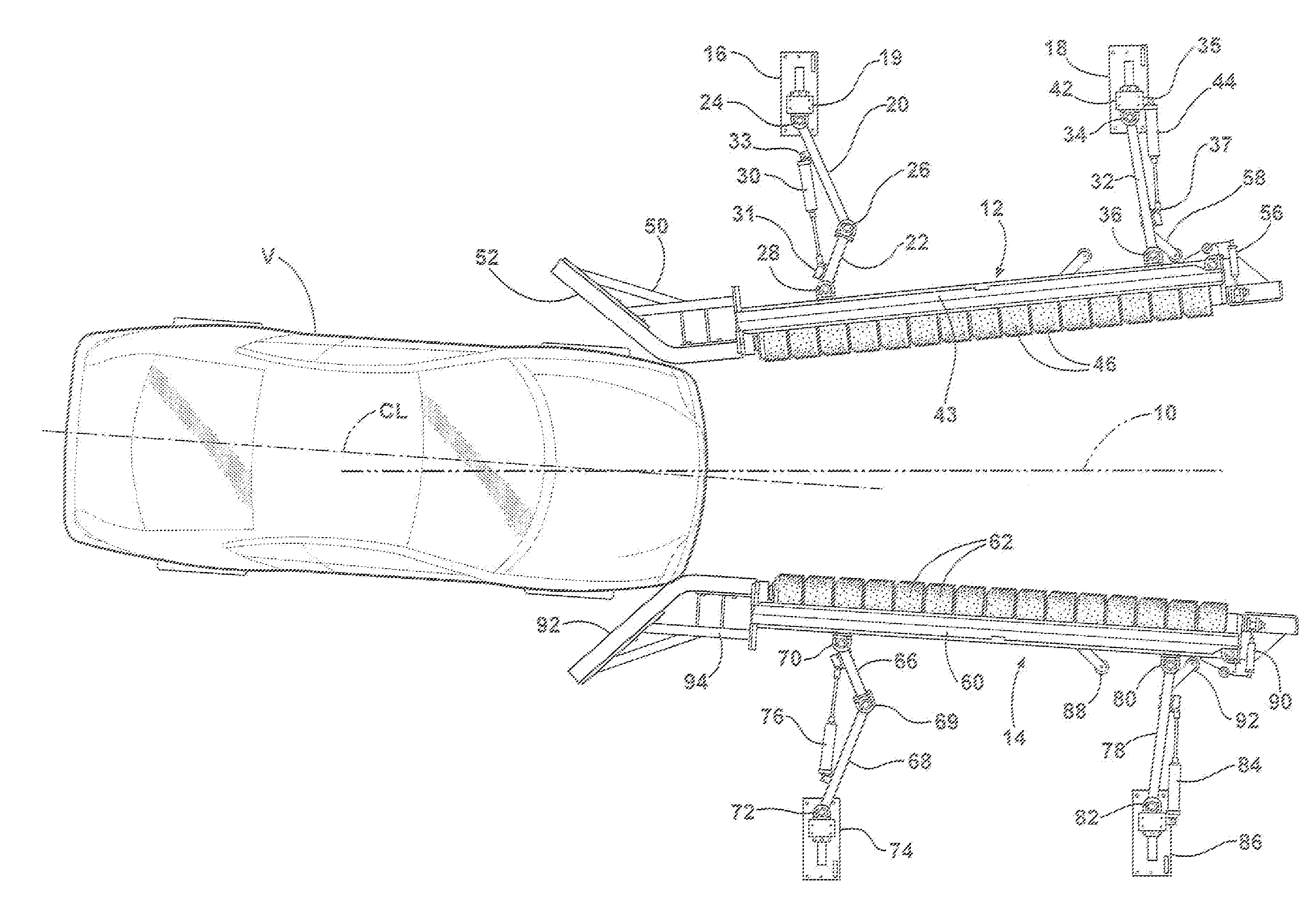
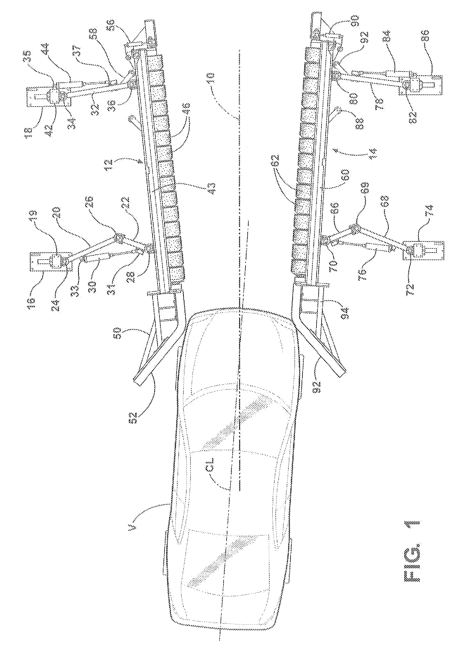
[0013]Referring to FIG. 1, there is shown in plan view a double-sided tire dressing system in which the designated path of travel 10 is shown essentially as a geometric center line between two mirror image applicator structures 12, 14. Describing structure 12 first, it comprises,a pair of anchor plates 16, 18 which are bolted to the floor of a car wash installation in parallel spaced relationship. Plate 16 incorporates a standard 19, to which one end of an arm made up of two portions 20, 22 is connected by pivot 24. The other end of the arm portion 20, 22 is connected by a pivot 28 to an elongate carriage 43. A knuckle 26 interconnects the portions 20, 22 to form a collapsible arm which, by virtue of the knuckle 26, can vary in effective length. In the embodiment shown, arm portion 20 is approximately 24¾ inches long from the center of pivot 24 to the center of pivot 26 and arm portion 22 is approximately 13½ inches long from the center of knuckle pivot 26 to the center of pivot 28....


PUM


Abstract

A tire dressing applicator station for use in car wash installations wherein the applicators are tolerant of large degrees of vehicle misalignment, misorientation and entry contact shock. In each applicator structure, an additional pivot or “knuckle” is placed in one of two support arms which are pivotally connected between floor anchors and an elongate mounting carriage to which the dressing applicator elements are attached. Flared tire guides are located on the entry ends of the applicator structures to make contact with the tires of approaching vehicles whereby one or both of the two applicator structures is / are reoriented as necessary to accommodate the actual location of the vehicle, whether it be on the intended path of travel or off to one side and / or angularly misoriented relative to die intended path of vehicle travel.

Description

FIELD OF THE INVENTION[0001]This invention relates to automatic vehicle treatment stations of the type found in commercial car washes and more particularly to a tire or wheel treatment device which absorbs shock forces due to vehicle entry and is tolerant of vehicle misalignment during treatment.BACKGROUND OF THE INVENTION[0002]In pending application U.S. patent application Ser. No. 12 / 062,996 filed Apr. 4, 2008 and assigned to Belanger, Inc. of Northville, Mich., there is described a system for effectively applying dressing, such as Armor All®, to the sidewalls of the tires on a motor vehicle. The device comprises the combination of two elongate applicator structures arranged in mirror image fashion on opposite sides of a vehicle path of travel. Each structure comprises a linear series of foam plastic applicator rollers arranged on a shaft attached to a carriage supported by a pair of parallelogram arms. These arms are, in turn, attached to anchor plates bolted to the floor of a ca...

Claims


Application Information

Patent Timeline
IPC IPC(8): B08B3/00
CPCB08B1/02B60S3/042B08B1/04B08B1/20B08B1/32
Inventor BELANGER, MICHAEL J.TOGNETTI, DAVID L.MORIN, MARK D.HINSON, MARSHALL L.
Owner PISTON OPW INC
Features
  • Generate Ideas
  • Intellectual Property
  • Life Sciences
  • Materials
  • Tech Scout
  • Unparalleled Data Quality
  • Higher Quality Content
  • 60% Fewer Hallucinations
Learn More