

Method and apparatus for reducing the appearance of skin markings
- Summary
- Abstract
- Description
- Claims
- Application Information
AI Technical Summary
Benefits of technology
Problems solved by technology
Method used
Image

Examples
Embodiment Construction
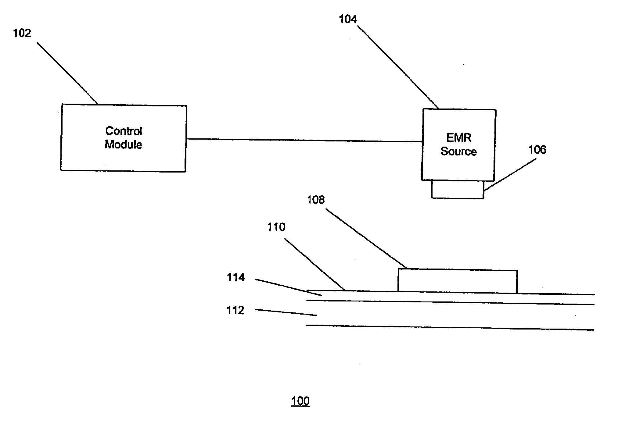
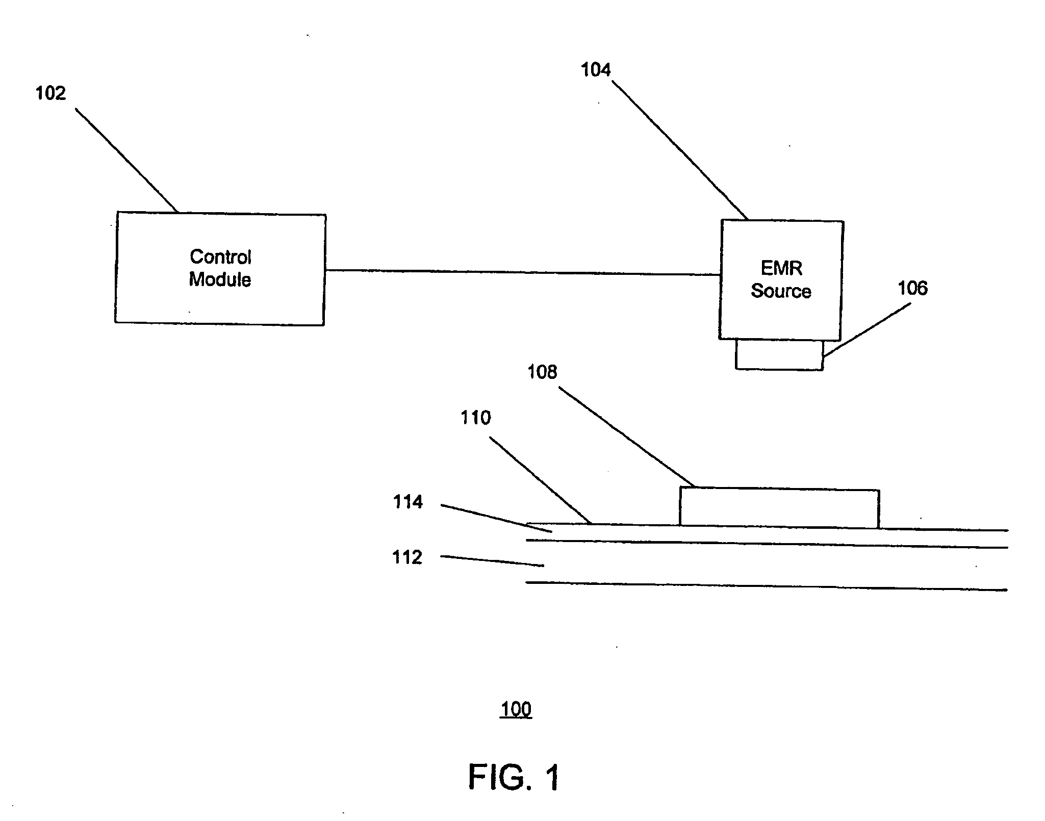
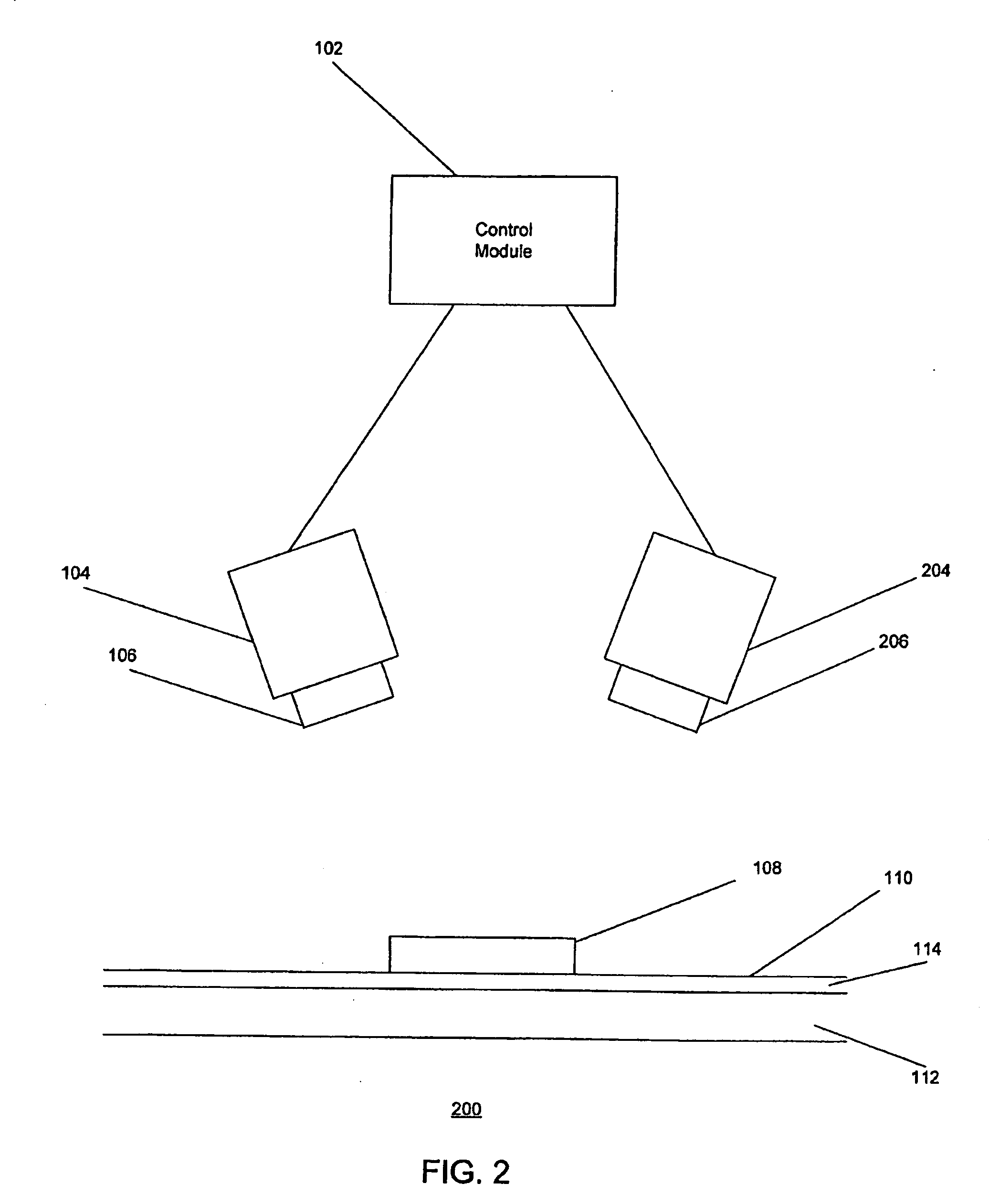
[0030]FIGS. 1, 2, 5 and 6 illustrate exemplary embodiments of methods and systems for dermatological treatment of a target area of skin. Generally, the exemplary methods and systems deliver an electromagnetic radiation to the patient's skin so as to induce thermal injury of dermal tissue of the skin, thus resulting in the reduction of skin markings. The skin markings may include tattoos, pigmented lesions, and the like. The pigmented lesions may include melasma, lentigines, and the like.
[0031]FIG. 1 illustrates a first exemplary embodiment of a dermatological treatment system 100 for conducting various dermatological treatments using electromagnetic radiation (“EMR”) to generate desired, target-selective photothermal skin damage of a target area according to the present invention. The system 100 may be used for a removal of unwanted pigment, a removal or reduction of the appearance of a tattoo, and / or similar dermatological applications. This system 100 can deliver EMR radiation to...
PUM
 Abstract
Description
Claims
Application Information