Cooling Device for Lamp with Power Light Emitting Diode

Inactive Publication Date: 2010-12-30
NICELUX
View PDF0 Cites 3 Cited by
  • Summary
  • Abstract
  • Description
  • Claims
  • Application Information

AI Technical Summary

Benefits of technology

[0019]The present invention is capable of cooling the heat caused by the power light emitting diode and stably keeping the lowered temperature. Heating is prevented so that the power light emitting diode can stably emit light of high brightness lengthen its durability, increase power efficiency, so that exchanging cost and repairing cost.

Problems solved by technology

But, even though the above light emitting diodes are widely used, for example in an electric sign, it has problems, such as, its brightness not being high enough the fulfill the required lighting standard of a street light or lamp, lacking stability as the brightness is easily affected by surrounding temperature.
The above power light emitting diode is suitable for street lights due to high brightness compared to the previous light emitting diodes, but emitting heat reaches 200? when switched on, and the caused heat shortens of durability of the light emitting diode and causes separation of the light emitting diode from the connecting clamp due to melting of soldered joint.
To prevent and cool the emitted heat above, an air-cooled system was installed to lamps using power light emitting diode, but the air-cooled system failed to overcome the above problems as the cooling effect was unsatisfactory and stability of the temperature was not obtained.
But the above previous invention stores the refrigerant separately to the above lamp light which complicates the formation of the device and increases the manufacturing cost.
Also, because the cooling system is of a one-sided formation, it cannot provide cooling water of a suitable temperature when the temperature of the cooling water is increased due to the emitted heat from the power light emitting diode, which causes change in temperature of power light emitting diode and in stability of brightness.

Method used


Image

  • Cooling Device for Lamp with Power Light Emitting Diode
  • Cooling Device for Lamp with Power Light Emitting Diode
  • Cooling Device for Lamp with Power Light Emitting Diode

Examples


Embodiment Construction

[0024]The present invention of the above formation is described in detail below referring to diagrams.

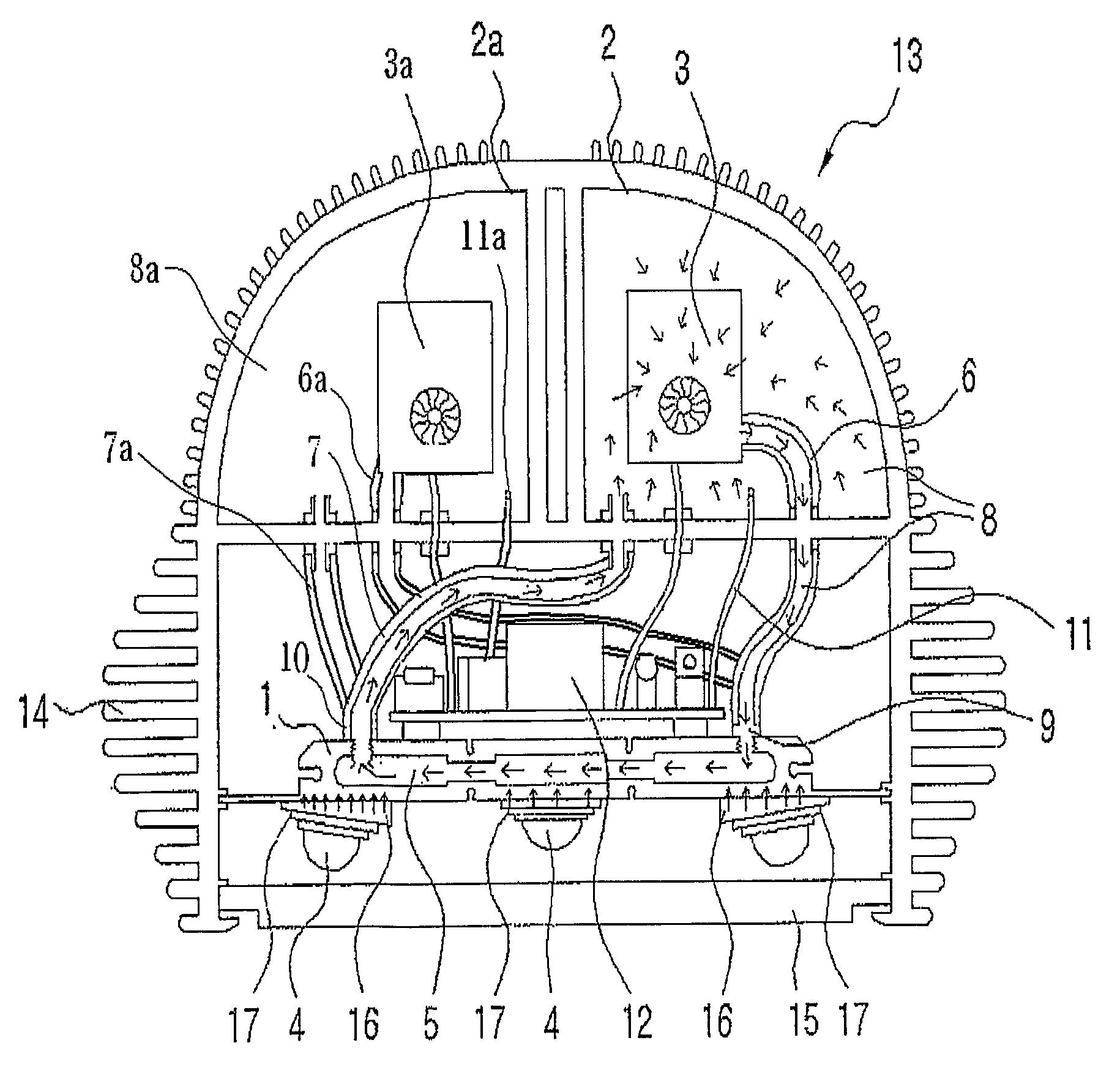
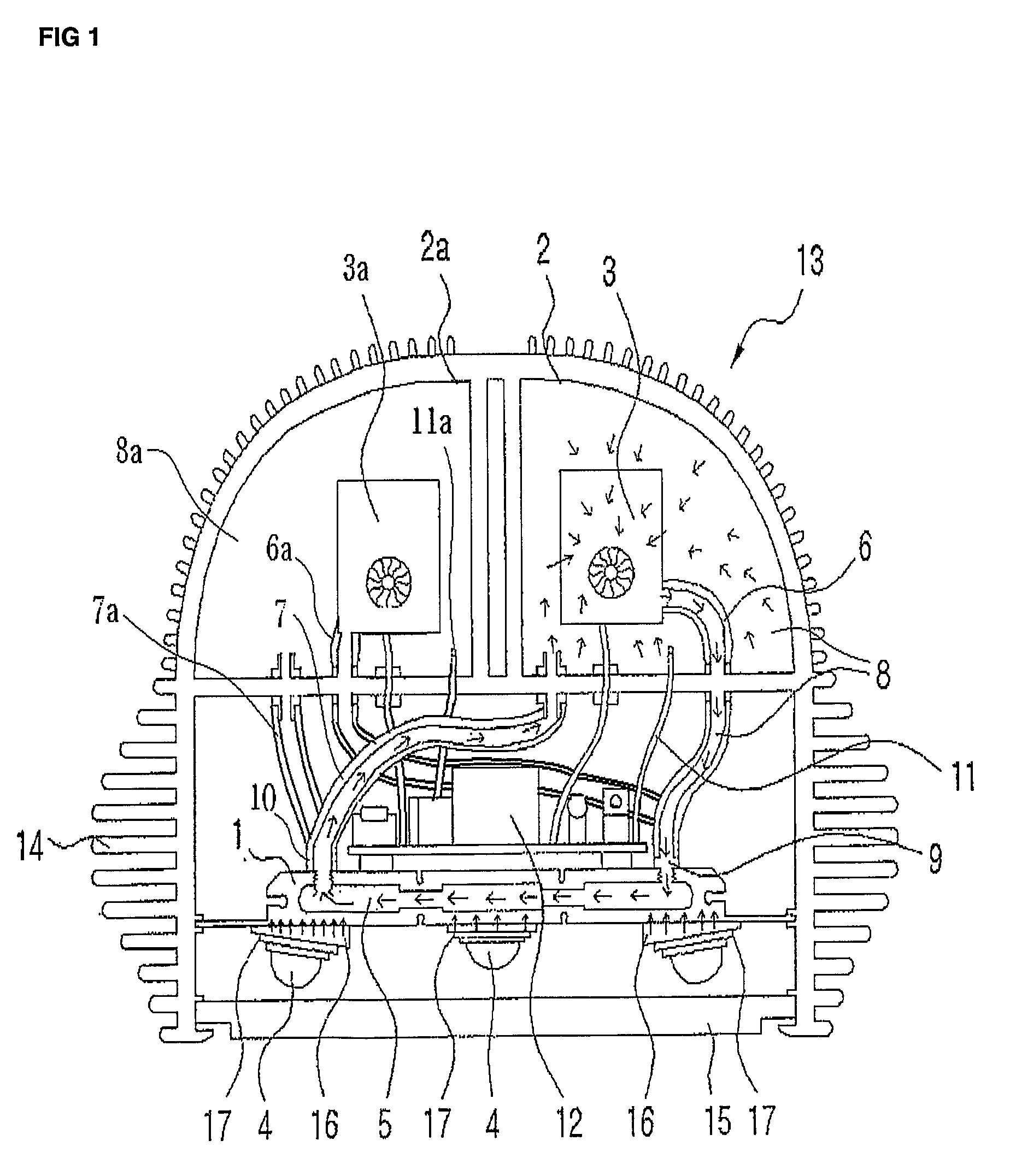
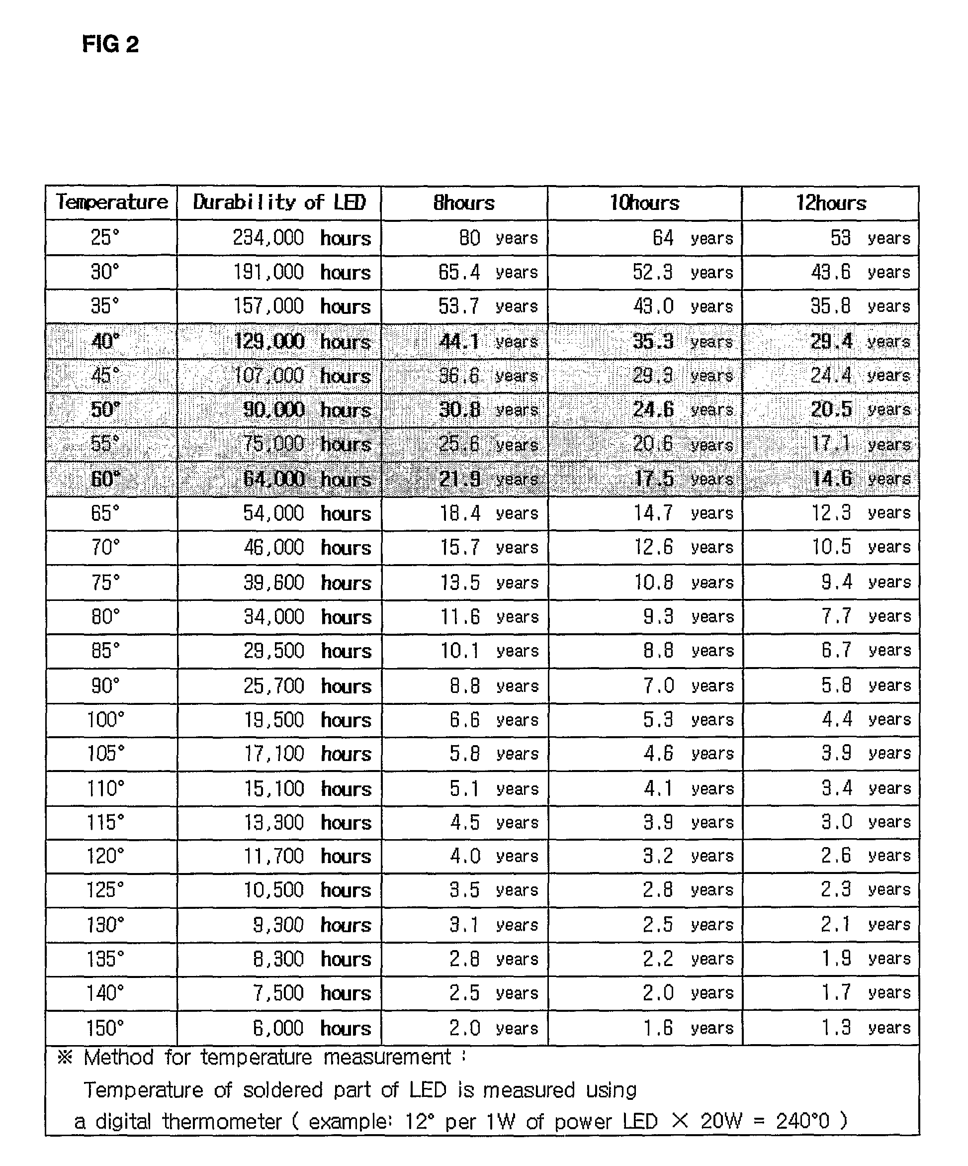
[0025]FIG. 1 is a cross-sectional view illustrating the cooling device of the lamp light inside the power light emitting diode, FIG. 2 is a diagram showing a durability chronological chart (by used time per day) according to the heating effect of the power light emitting diode, FIG. 3 is a diagram showing energy and light efficiency according to the heating effect, and FIG. 4 is a diagram showing comparison between the present and the previous cooling devices.

[0026]As illustrated in FIG. 1, an air-cooled insulating board (14) is formed on the surface of semi-circular body (13); cooling water container (2) and cooling water container A(2a) comprising of cooling water (8)(8a) are formed inside the above semi-circular body (13); and on the upper part of inside the above cooling water container (2) and cooling water container A(2a) are installed a circulating pump (3)(3a) for circulatin...


PUM


Abstract

The present invention refers to a cooling device for lamp with power light emitting diode comprising of a number of cooling water containers containing a circulating pump and a temperature sensor installed to a particular body with lighting installed. Cooling water incoming pipe and extruding pipe connected to the cooling water container above are connected to a cooling water circulation passage of power light emitting diode, so that cooling water flows in circulation within the circulation passage. When the temperature of the circulating cooling water rises to a certain point, the circulation of the particular cooling water container stops operating, and another cooling water container is operated to keep the thermal power light emitting diode at room temperature, so that the durability of the power light emitting diode is lengthened, and maximizes the cooling effectiveness and power-saving.

Description

TECHNICAL FIELD[0001]The present invention refers to a cooling device for lamp with power light emitting diode comprising of a number of cooling water containers containing a circulating pump and a temperature sensor installed to a particular body with lighting installed. Cooling water incoming pipe and extruding pipe connected to the cooling water container above are connected to a cooling water circulation passage of power light emitting diode, so that cooling water flows in circulation within the circulation passage. When the temperature of the circulating cooling water rises to a certain point, the circulation of the particular cooling water container stops operating, and another cooling water container is operated to keep the thermal power light emitting diode at room temperature, so that the durability of the power light emitting diode is lengthened, and maximizes the cooling effectiveness and power-saving.BACKGROUND ART[0002]Generally, light emitting diode (LED) forms minorit...

Claims


Application Information

Patent Timeline
IPC IPC(8): F28D15/00
CPCF21V29/30F28D15/00F21Y2101/02F21W2131/103F21V29/57F21V29/59F21Y2115/10F21V23/0442F21V29/58
Inventor KWON, HEUI KWANG
Owner NICELUX
Why Eureka
Try Eureka