LED module

a technology of led modules and diodes, applied in semiconductor devices for light sources, instruments, lighting and heating apparatus, etc., can solve problems such as discomfort and glar

Inactive Publication Date: 2010-12-30
FU ZHUN PRECISION IND SHENZHEN +1
View PDF3 Cites 32 Cited by
  • Summary
  • Abstract
  • Description
  • Claims
  • Application Information

AI Technical Summary

Benefits of technology

[0005]A typical LED includes an LED die emitting light and a transparent encapsulant enveloping the LED die. The encapsulant protects the LED die from contamination and damage, and converges most of the light emitted from the LED die around an optical axis of the LED into a narrow beam. The encapsulant keeps a peak intensity of the light occurring around the optical axis of the LED, which easily results in a discomfortable glare.

Problems solved by technology

The encapsulant keeps a peak intensity of the light occurring around the optical axis of the LED, which easily results in a discomfortable glare.

Method used


Image

  • LED module
  • LED module
  • LED module

Examples


Embodiment Construction

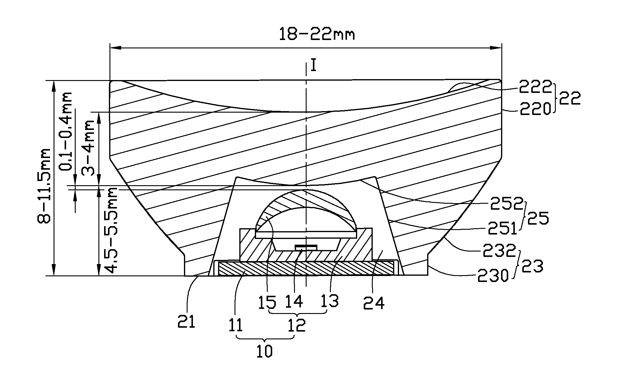
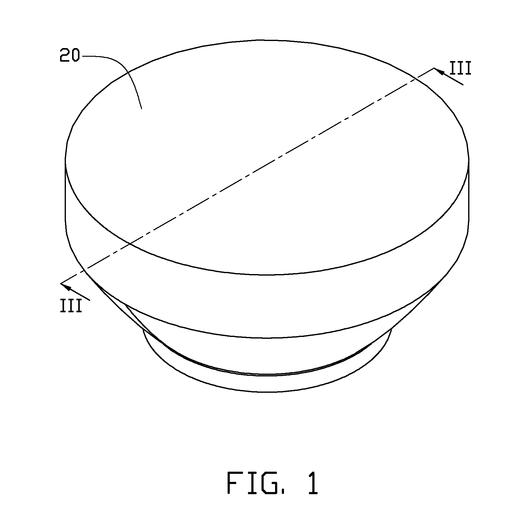
[0012]Referring to FIGS. 1 and 3, an LED (light emitting diode) module is illustrated in accordance with an embodiment of the disclosure. The LED module includes an LED assembly 10 (see FIG. 3) and a lens 20 located over and enclosing the LED assembly 10. The LED assembly 10 includes a plate-shaped printed circuit board 11 and an LED 12 attached to a top surface of the printed circuit board 11. The LED 12 has a vertical optical axis I. The LED 12 includes a rectangular base 13 having a recess (not labeled) recessed downwards from a top surface thereof, an LED die 14 secured in the recess of the base 13 and an encapsulant 15 enveloping the LED die 14 and fixed on a top of the base 13. The encapsulant 15 is dome-shaped for being acted as a primary convex lens to spread light emitted from the LED die 14 into a divergent pattern.

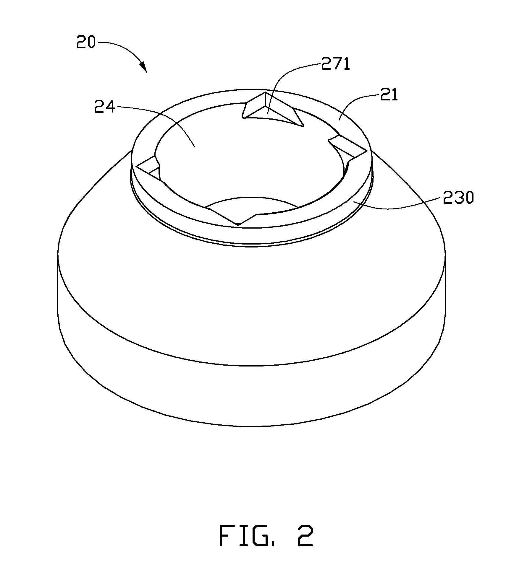
[0013]Also referring to FIG. 2, the lens 20 may be integrally made of a light-permeable material, such as PC or PMMA. The lens 20 has a bowl-like configuration....


PUM


Abstract

An LED module includes an LED and a lens located over and enclosing the LED. The lens includes a surface of incidence facing the LED for an incidence of light emitted from the LED and a surface of emission for an emission of the light out of the LED module. The surface of incidence has a convex spherical surface, and the surface of emission has a concave spherical surface corresponding to the convex spherical surface. The convex spherical surface refracts the light incident thereon to redirect the light to the concave spherical surface. The concave spherical surface spreads the light into a wide and uniform beam. The surface of emission further has a first cylinder extending downwardly from an outer edge of the concave spherical surface. A totally reflective coincoid extends downwards from the first cylinder to a bottom of the LED module.

Description

BACKGROUND[0001]1. Technical Field[0002]The disclosure relates to a light-emitting device and, more particularly, to an LED (light emitting diode) module.[0003]2. Description of Related Art[0004]LEDs (light emitting diodes), available since the early 1960's, have been increasingly used in a variety of application fields and are intended to be a high quality replacement for conventional light sources due to high light-emitting efficiency, environmental friendliness, and low power consumption.[0005]A typical LED includes an LED die emitting light and a transparent encapsulant enveloping the LED die. The encapsulant protects the LED die from contamination and damage, and converges most of the light emitted from the LED die around an optical axis of the LED into a narrow beam. The encapsulant keeps a peak intensity of the light occurring around the optical axis of the LED, which easily results in a discomfortable glare.[0006]What is needed, therefore, is an LED module which can overcome...

Claims


Application Information

Patent Timeline
Patent Type & Authority Applications(United States)
IPC IPC(8): H01L33/60H01L33/58
CPCF21K9/00F21V5/008F21V5/04F21V7/0091G02B19/0061F21Y2101/02H01L33/58H01L33/60G02B19/0028F21V13/04F21K9/69F21Y2115/10
Inventor WANG, ZHONG-QINGZHANG, HAI-WEI
Owner FU ZHUN PRECISION IND SHENZHEN
Why Eureka
Try Eureka