Light source device, video projector and video projection method

a technology of video projection and light source device, which is applied in the direction of picture reproducers using projection devices, lighting and heating apparatus, instruments, etc., can solve the problems of lack of red luminance of various red fluorescent materials, difficulty in achieving smallness, lightness and inexpensiveness of the entire apparatus, and difficulty in achieving small number of parts

Active Publication Date: 2010-12-30
CASIO COMPUTER CO LTD
View PDF19 Cites 78 Cited by
  • Summary
  • Abstract
  • Description
  • Claims
  • Application Information

AI Technical Summary

Benefits of technology

[0008]One of objects of the present invention is to provide a light source device, a video projector and a projection method, which are capable of compensating for any possible uneven luminance for each primary color component obtained from a single light source and making color reproducibility compatible with the brightness of a projection image.
[0011]According to a third aspect of the present invention, there is provided a video projection method for a video projector. The video projector includes: a light source device including: a first light source configured to emit a first source light in a first wavelength range; a source light generator configured to generate, from the first light, a color-varying source light having time varying color; and a second light source configured to emit a second source light in a second wavelength range that is different from the first wavelength range; a video interface configured to receive a video signal; and a projector unit configured to generate, from output source light output from the light source device, a color photo image in accordance with the video signal and project the color photo image. The method includes: controlling driving timing for turning on and off each of the first light source and the second light source so as to cyclically select one of the color-varying source light and the second source light to be output as the output source light.

Problems solved by technology

Displaying a color image with a projection type display apparatus requires planar light sources which emit respective primary R, G and B light, and corresponding spatial light modulators, which may result in an increased number of parts and difficulty in achieving smallness, lightness and inexpensiveness of the entire apparatus.
However, if the above-described system is employed in practice, various red fluorescent materials, which are currently known in the art, are lacking in red luminance since their emission efficiency is remarkably lower than that of other green and blue fluorescent materials.
As a result, when a bright projection image is to be obtained by preferring luminance, there arises a problem of white balance collapse and hence low color reproducibility.
On the other hand, when the white balance and hence the color reproducibility are emphasized, the entire luminance is lowered to meet a red image having a low luminance, which results in a dark image.

Method used


Image

  • Light source device, video projector and video projection method
  • Light source device, video projector and video projection method
  • Light source device, video projector and video projection method

Examples


first modification

[0088]Next, a first modification according to the embodiment will be described.

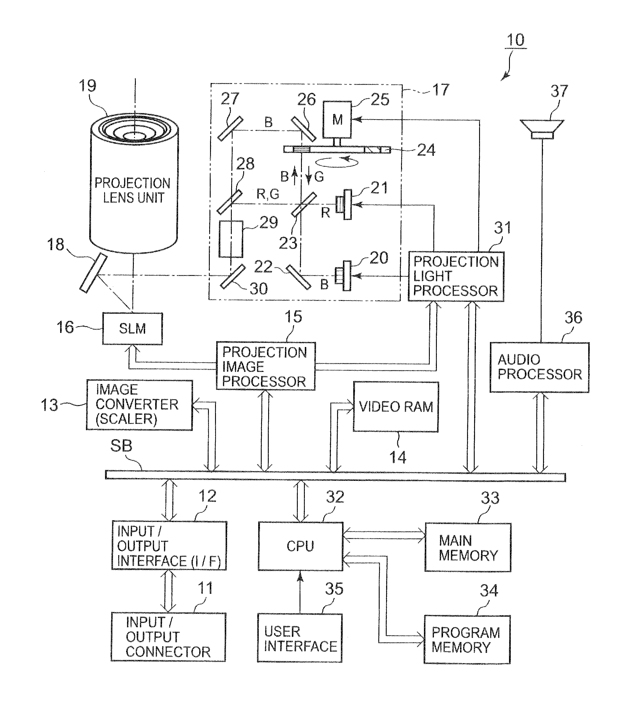
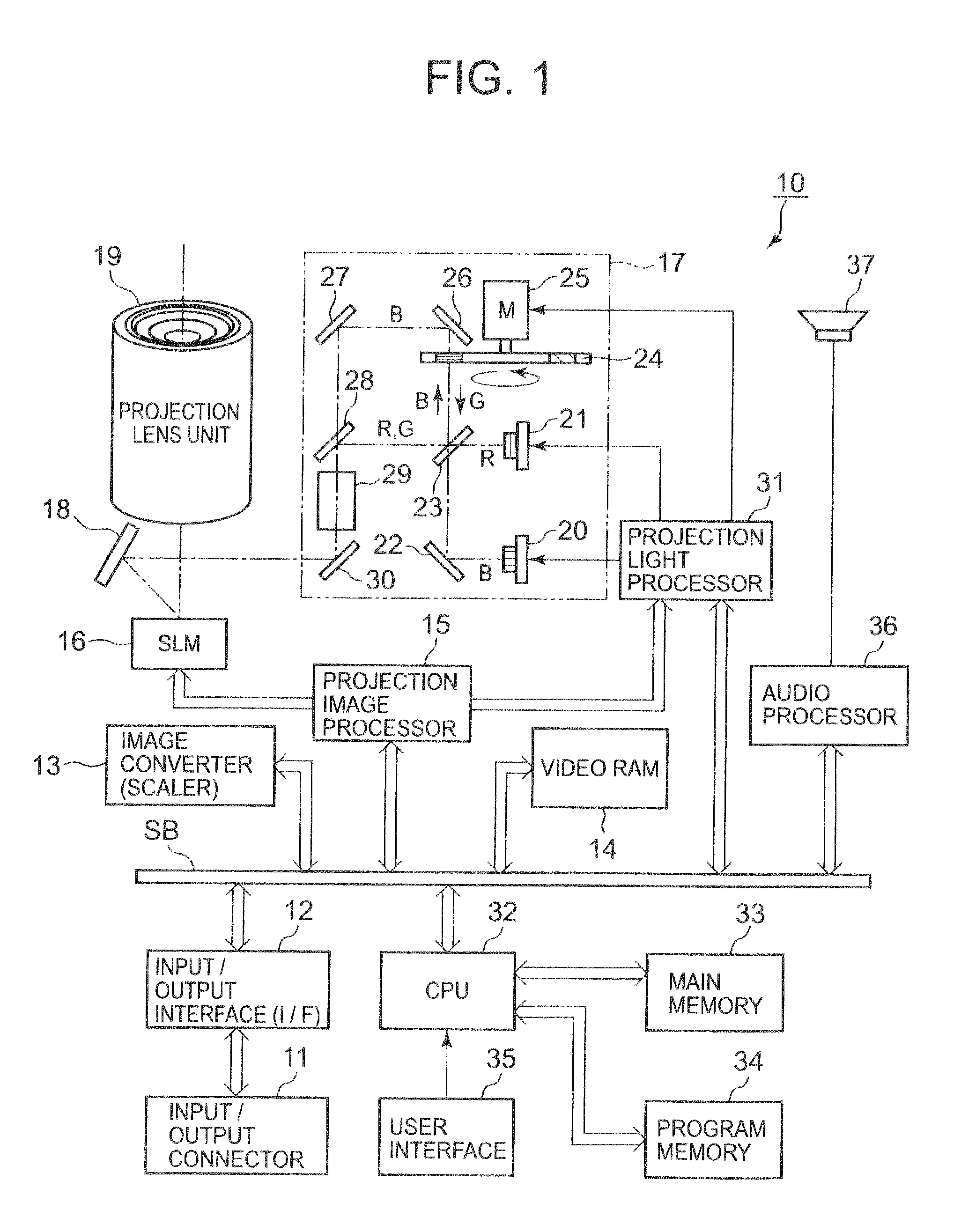
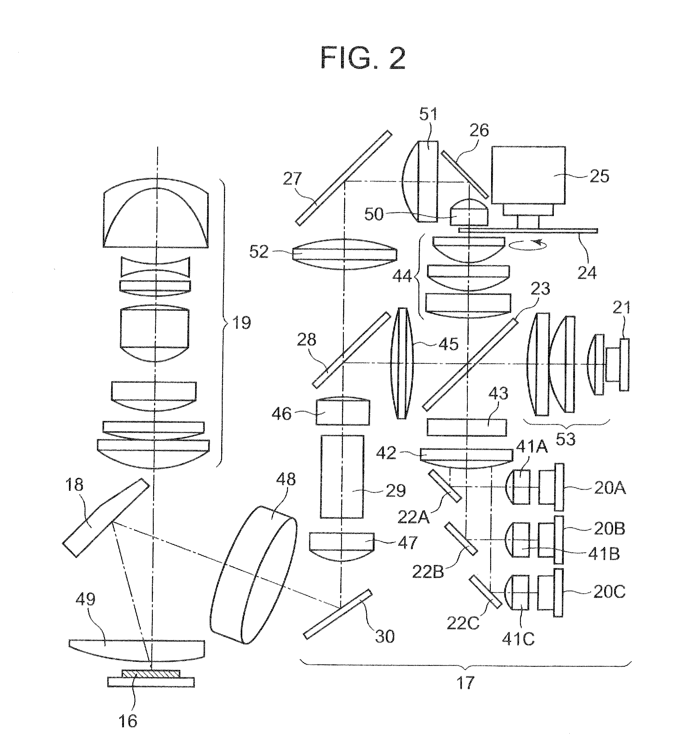
[0089]In this modification, it is assumed that the data projector apparatus 10, particularly, the light source unit 17, has the same basic configuration as those shown in FIGS. 1 and 2, and explanation thereof will be omitted.

[0090]It is here assumed that a time ratio between time slots during which primary R, Y (yellow), G and B images constituting one frame of a color image to be projected (hereinafter referred to as “R field, Y field, G field and B field”) is 10.5:10.5:8:7.

[0091]In other words, with respect to one rotation of 360 degrees of the color wheel 24 which is being rotated at a constant speed, a time ratio r:y:g:b between R field, Y field, G field and B field becomes 105 degrees:105 degrees:80 degrees:70 degrees in terms of a center angle of the color wheel 24.

[0092]Section (A) of FIG. 5 shows a color of source light irradiated onto the micro mirror device 16. As shown in the figure, a control...

second modification

[0109]Next, a second modification according to the embodiment will be described.

[0110]In this modification, it is assumed that the data projector apparatus 10, particularly, the light source unit 17, has the same basic configuration as those shown in FIGS. 1 and 2, and explanation thereof will be omitted.

[0111]It is here assumed that a time ratio between time slots is during which primary R, W (white), Y (yellow), G and B images constituting one frame of a color image to be projected (hereinafter referred to as “R field, W field, Y field, G field and B field”) is 10.5:5.5:5:8:7.

[0112]In other words, with respect to one rotation of 360 degrees of the color wheel 24 which is being rotated at a constant speed, a time ratio r:w:y:g:b between R field, W field, Y field, G field and B field becomes 105 degrees:55 degrees:50 degrees:80 degrees:70 degrees in terms of a center angle of the color wheel 24.

[0113]FIG. 6 shows a configuration of a color wheel 241 replaced for the color wheel 24. ...

third modification

[0137]Next, a third modification according to the embodiment will be described.

[0138]In this modification, it is assumed that the data projector apparatus 10, particularly, the light source unit 17, has the same basic configuration as those shown in FIGS. 1 and 2, and explanation thereof will be omitted.

[0139]Here, boundary time slots (hereinafter referred to as “spoke time slots”) are provided for respective time slots during which primary R, G and B images constituting one frame of a color image to be projected are projected (hereinafter referred to as “R field, G field and B field”), with one frame being constituted by 6 R, Y (yellow), G, Y (yellow), B and M (magenta) fields in total, and it is assumed that a time ratio between the R, Y, G, Y, B and M fields is 13:1:14:1:6:1.

[0140]In other words, with respect to one rotation of 360 degrees of the color wheel 24 which is being rotated at a constant speed, a time ratio r:y:g:y:b:m between the R field, Y field, G field, Y field, B f...


PUM


Abstract

A light source device includes: a first light source configured to emit a first source light in a first wavelength range; a source light generator configured to generate, from the first light, a color-varying source light having time varying color; a second light source configured to emit a second source light in a second wavelength range that is different from the first wavelength range; and a light source controller configured to control driving timing for turning on and off each of the first light source and the second light source so as to cyclically select one of the color-varying source light and the second source light to be output as an output source light.

Description

CROSS-REFERENCE TO THE RELATED APPLICATION(S)[0001]The present application is based upon and claims priority from prior Japanese Patent Application No. 2009-156091, filed on Jun. 30, 2009, the entire content of which are incorporated herein by reference.BACKGROUND[0002]1. Field of the Invention[0003]The present invention relates to a light source device, a video projector and a video projection method, which are adaptable for a digital light processing (DLP (registered trade mark)) type data projector (video projector).[0004]2. Description of the Related Art[0005]Displaying a color image with a projection type display apparatus requires planar light sources which emit respective primary R, G and B light, and corresponding spatial light modulators, which may result in an increased number of parts and difficulty in achieving smallness, lightness and inexpensiveness of the entire apparatus. For the purpose of solving such a problem, a system has been proposed, in which a light emitting...

Claims


Application Information

Patent Timeline
Patent Type & Authority Applications(United States)
IPC IPC(8): H04N9/31F21V9/00F21V9/16H05B37/02
CPCG03B21/204H04N9/3197H04N9/3161
Inventor SHIBASAKI, MAMORU
Owner CASIO COMPUTER CO LTD
Why Eureka
Try Eureka